3D Sliced Image - Progressively Weaker/Extra Cleanup Passes?

Machine - 50w Non-Mopa Raycus Galvo laser. Triumph vendor, JCZ control, 200mm lens.

I’m attempting to run a 3D sliced image on the machine, and was playing around with cleaning passes. Cleanup all, cleanup only recent cut, speed and power. Right now I’m roughing at 2000mm/s, 50hz and 95% power. Cleaning at 3000mm/s, 100hz, 25% power, cleaning every 2 passes.

The machine will do two roughing passes, a cleanup pass and repeat for a little while, then it will do like…two passes at the cleanup settings and then an ultra faint third cleanup pass? Video doesn’t do it justice obviously, but if say the rough is 100%, and the cleanup around 30%, I’d say it’s doing like 100,100,35,30,30,10, repeat. Like it’s doing a cleanup of the cleanup? I don’t know how better to describe it, but it’s weird. I don’t think I’m outside the parameters of the fiber source, but I’m not 100% sure. I’ve checked for dirty lens, don’t see anything.

Anyone ever seen anything similar?

Is that an F200mm or coverage?

Although unlikely, ensure it’s not going out of focus during the run as it gets deeper.

An F254mm lens has an approximate depth of focus of almost 4.5mm, so I doubt that’s the problem. If you were using an F100mm lens the dof is about 0.74mm.

My MOPA has protections from heat and reflections that will reduce the power. Most fiber machine have a threshold where they will reduce the output, depending on frequency.

Suggest you find a manual for your fibers source, all of this should be in there.


It might help us help you if you can post your .lbrn2 file so we can examine it. You should be able to just drag and drop it onto the reply window.

:grinning_cat:

Sorry, don’t have the file with me at the moment - not on campus (school shop/STEM teacher) - I don’t remember it doing it at lower power settings but we’d been stepping up power and fiddling with different cleanup pass settings, so it’s very possible we’ve trigged some sort of heat protection. It does it early in the cut (like first 4-5 passes) and it sporadically goes back to full power then back down to the barely there settings, which fits with thermal protections.

I do have the exact model number and looked it up when we first got it, so I’ll dig at school Monday. My main concern was that I’d damaged something some how.

Could you clarify on F200 vs 200 field lens? I know it came with a 110 and 200, and from the description I believe that is the size of the cutting area capability but maybe I’m mistaken. A little google-fu tells me this is probably an F290 lens, and I’m now suspecting I’d probably be better off swapping to the 110/F160 lens for brass coins.

Update, scrolled through old photos and found the model number - Raycus RFL-P50QB. Frequency is what I remember last time I looked this up, 50 to 100khz. Should I be keeping a little further away from the edge margins? I’m running roughing at 50khz and clean at 100khz, I can pull back a little, and turn down power from 95%. Was running 0.05mm overlap, but not sure that makes a huge difference other than run time.

I’m not sure what you’re describing, but I can say this-

I got fooled/confused a lot early on where I thought there was something wrong with the beam power- parts of the cut line went from bright blue to more dim yellow.

It was actually the coin surface overheating. The laser pulse needs to hit cold metal to ablate a particle off it. Starting from it in a melt-y state actually won’t cut, and can even melt into the cut zone.

You source manual is here.

I’d guess, from the manual, that 50kHz would be you’re most powerful pulses/s.


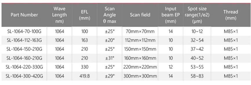
This is from Cloudray, showing lens focal length (EFL) and coverage (scan field) for a few lenses.

It shows the focal length and coverage area. Notice there are two 210mm lenses, depending on your available scan range.

Notice your spot size with one of your lenses, then the other lens. Reducing the lenses focal length will make the spot and the depth of focus get smaller. You can use this with your Raycus manual to compute approximate spot size… The more accurate the data, the more accurate the results.

My spot size of an F254mm is about 30 microns whereas an F100mm lens is about 15 microns. Changing spot size puts the same amount of power over a different size area.

Cutting the diameter in half, going from 30 microns to 15 microns, has an apparent power increase of 4 times. Same power, just a smaller area, but the operator will notice it.

I need room for me to see and have the ability to get in there, so I pretty much use an F254mm most of the time… It’s got a pretty small are and a good depth of focus.


This is a link to a commercial place, but gives a pretty good explanation of what an F Theta is/does.

Probably like the rest of us, you damaged your brain trying to figure this out. :face_with_spiral_eyes:

As far as I know these have reflection and overheat sensors to prevent you from doing any damage. These are pretty tough, so I doubt you could have damaged it.


It seems relatively easy but you have to deal with heat build up, discoloring, warping and getting the settings where you don’t engrave through the coin, like I’ve done. :joy_cat:

There is a couple commercial sales sites that do have some suggested settings, might want to look there and see if that helps.

Material Settings on the ComMarker B6 60W MOPA Fiber Laser

Thunder laser cutter settings for different materials

Hope this helps.

:grinning_cat:

This definitely gives me a few things to pick at, first and foremost I think it’s time to examine my lens’ a little closer and see exactly what I’m working with. Thanks for giving me a few things to try!

No perspiration … hang in there.

:grinning_cat: