3 Sections:
The Machine
The Problem
What I’ve tried
The Machine:
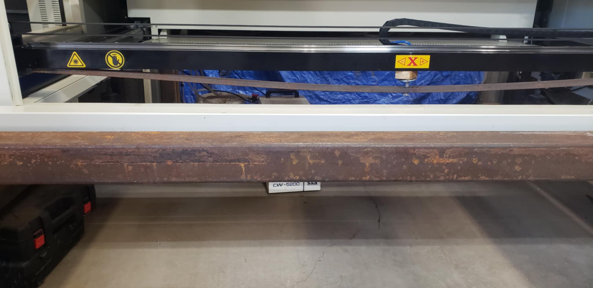
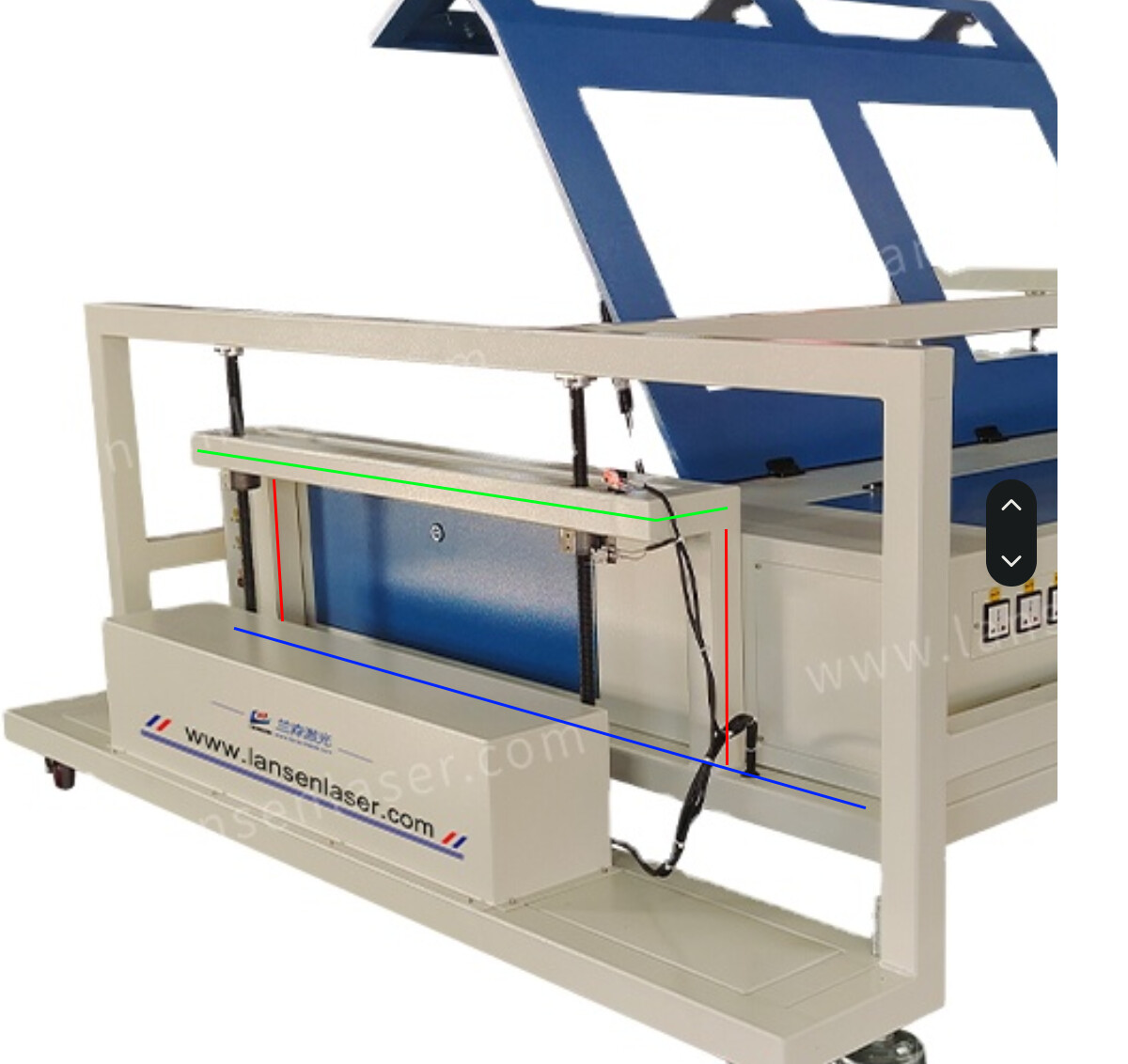
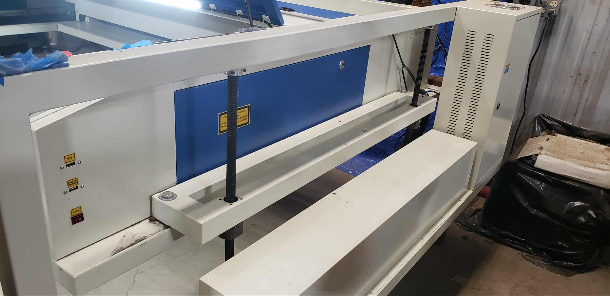
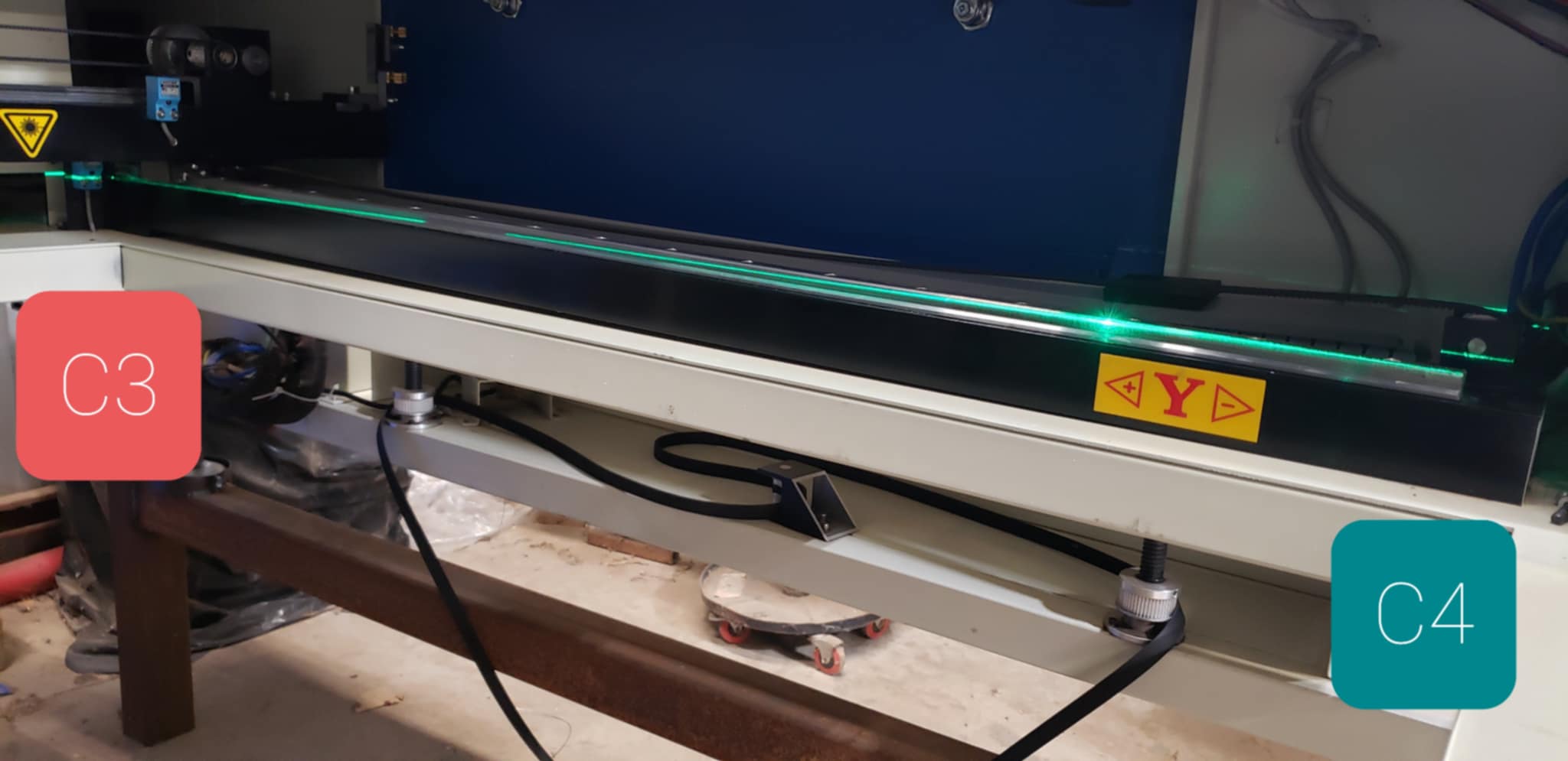
The working area is 1600mm by 1000mm and is meant to engrave objects that can be wheeled underneath. The Z axis moves the laser/gantry frame up and down while the outside frame remains still.
It had an inherent design flaw which caused it be unstable while in motion and induced vibration. I modified the machine by removing the 2 posts (2 on both sides, 4 in total) shown by the red lines. This fixed my instability issues caused from vibration.
I’m sharing this for context of my situation. I didn’t directly modify the frame in which the laser and rails/gantry sit on. It’s as if the machine has 2 frames now. All I did was take an cut off wheel to the red bar while the machine sat on cinder blocks.
I’m unsure if I caused the issue with C4 but it’s very likely it was there all along. I simply don’t know.
The Problem:
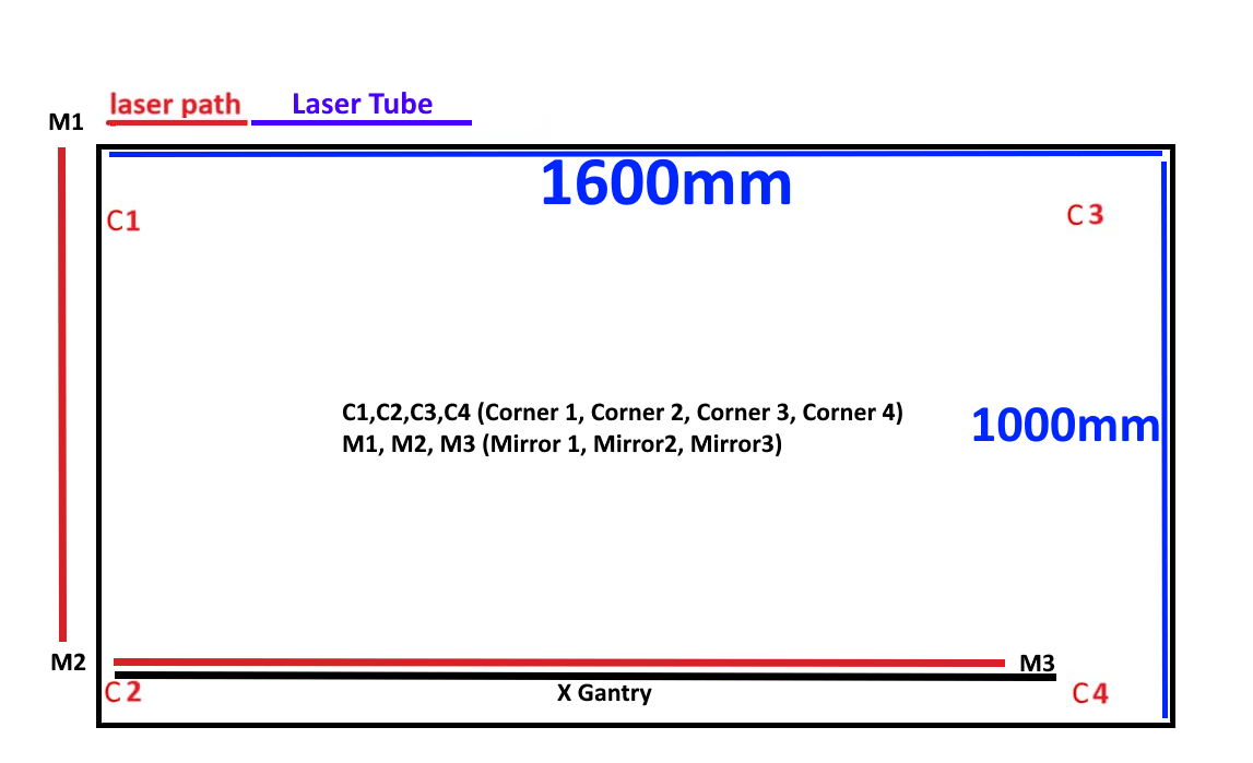
Too make it easier to explain things I will share this diagram
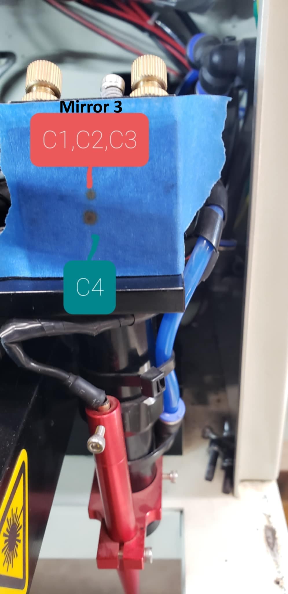
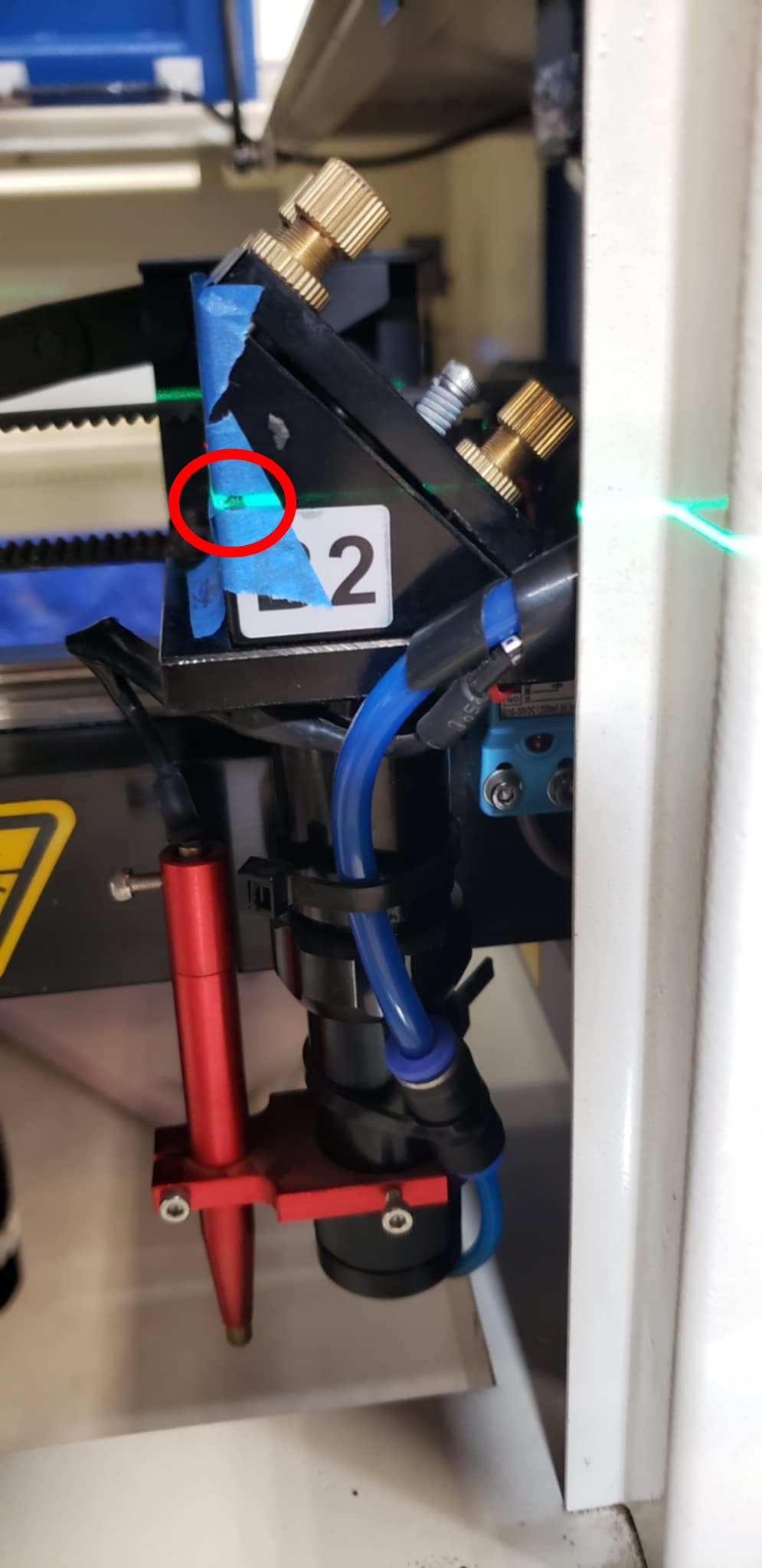
Making M3 co-planar on all 4 corners. In the photo below, I used a 360 laser level and made the black dot (drawn onto the blue tape) perfectly lined up when M3 was on all 4 corners. I did this by adjusting the lead screws the machine sits upon which touch the ground. Making the machine co-planarseemed to have no effect on the C4 burn.
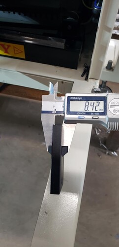
I removed the gantry shims at C4 and in between C3 and C4. These are about 8.4mm thick and dropped the rail in C4. This seemed to have little of the desired effect. NOTE, this was done before I made M3 co-planar on all 4 corners.
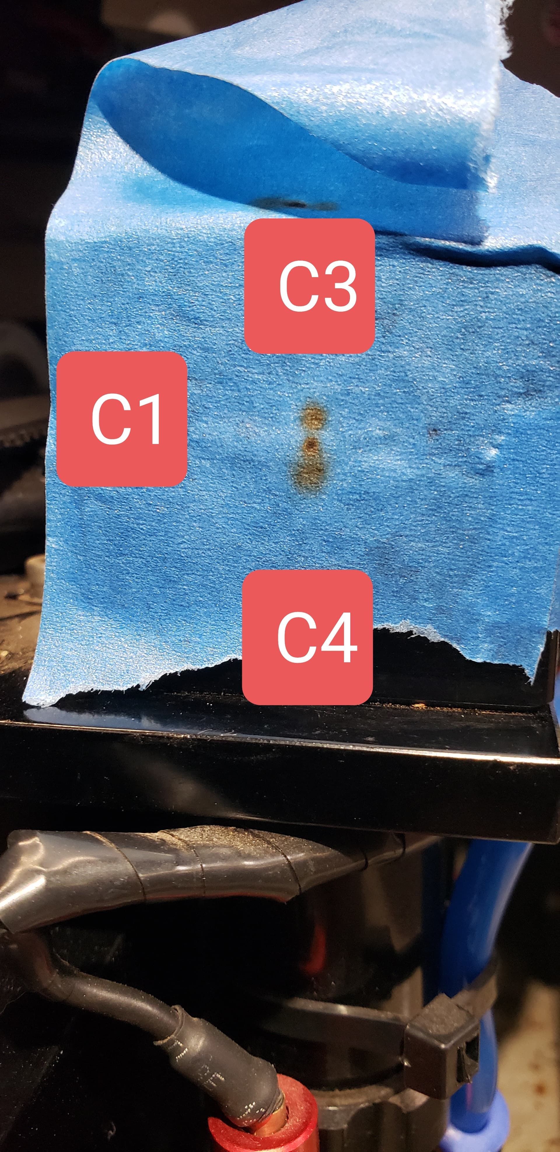
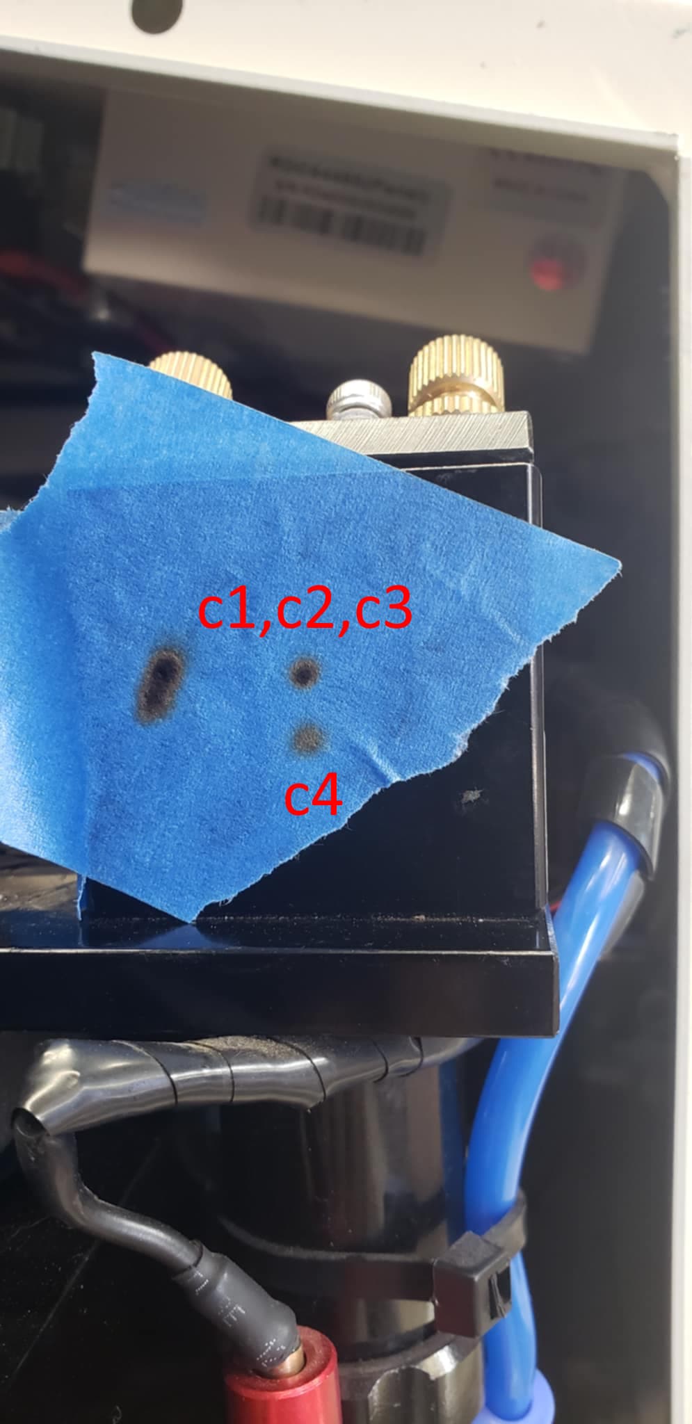
With the help of ednisley (I’m sure he’s sick of me by now , he’s spent many hours helping me) I adjusted M1 to try and pull C4 burn closer to the other burns. This was unsuccessful and the best I was able to do was get C3 2.5mm above concentric center (C1) and C4 2.5mm below concentric center
I’m a bit unsure of what is going on to say the least. My best guess at this point is something weird is going on with M2. But to say I have no idea what is going on would be an understatement
As @austen notes, over the past few weeks we’ve gone through all the usual “fixes” for the Dreaded Fourth Corner Problem to no avail.
In particular:
The mirrors / beam path have been aligned and that is not the problem
Tweaking Mirror 1 by the usual itsy does not have the desired effect
Stressing the frame in various ways does not change anything useful
Having already tweaked the machine into far better condition than usual, all those suggestions are not relevant unless you can think of a specific test to show otherwise …
I have seen this corrected by shimming the correct end of the tube. I don’t think that’s what I’d call a good fix, but I have seen some success. If you’re out of options, then maybe it’s something you can think about.
Yes it is, but if you don’t modify M1, then the path can be lowered by adjusting the tube. I don’t like this and have never had to use it, but I’ve seen it multiple times.
If you don’t want to try it, I’m not sure what to suggest. Seems like you and @ednisley have done all the other alignments.
If it’s as you both state, aligned properly. The only thing that can cause this is the lack of it being 3d square.
I’ll run with this and see if something pops up in my mind about what to check.
It does. You can correct for a misaligned beam axes. The last fixed mirror that the beam reflects from can be any angle, within limits. 45 degrees makes this easier to deal with.
Imagine tilting your tube 45 degrees, you don’t think that will change the beams impact for all the mirrors following?
It’s relatively moot anyway as you’ve tried this. In any event the beam is straight, finding where is goes wrong might be a bit of an issue, especially with large machine.
So I worked the machine again today to no avail. To say the least, I’m still baffled.
I tried 2 methods today to see if I could fix the issue.
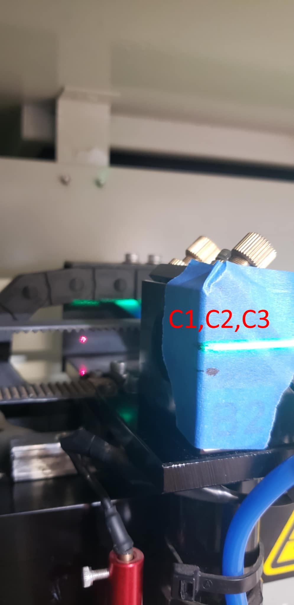
1. Tilting the laser tube
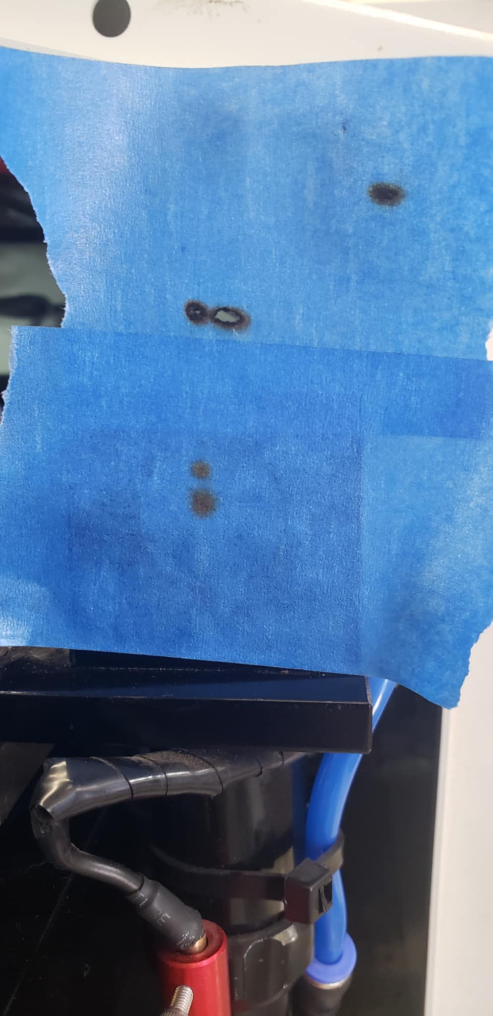
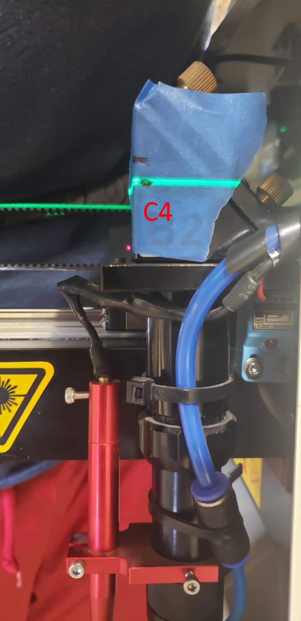
This appeared to have little to no effect. The 4th corner about 5mm below the concentric center. My thought was to aim the laser higher to try and bring the 4th corner closer/higher to the concentric center as shown in the image below.
It does appear that the dot is closer (about 3.5mm away now, to the best of my ability measuring with calipers) but I started to run out of room to further tilt the beam upwards and still hit the mirrors. I thought maybe I could have a defective laser tube that is not shooting a straight beam, so I rotated it 180 degrees to see if the laser path changed, but it didn’t.
So it appears tilting the tube might have slightly helped? Or it could be an error in my mirror tuning. The laser tube is well out of coplanar from the gantry’s at this point so I’m not sure why the C4 burn appears to be moving closer. It was definitely harder to tune the burns to be concentric and doesn’t feel right. Below is the burn result
2. Dropping the 4th corner 6mm to try and bring the 4th burn 6mm up
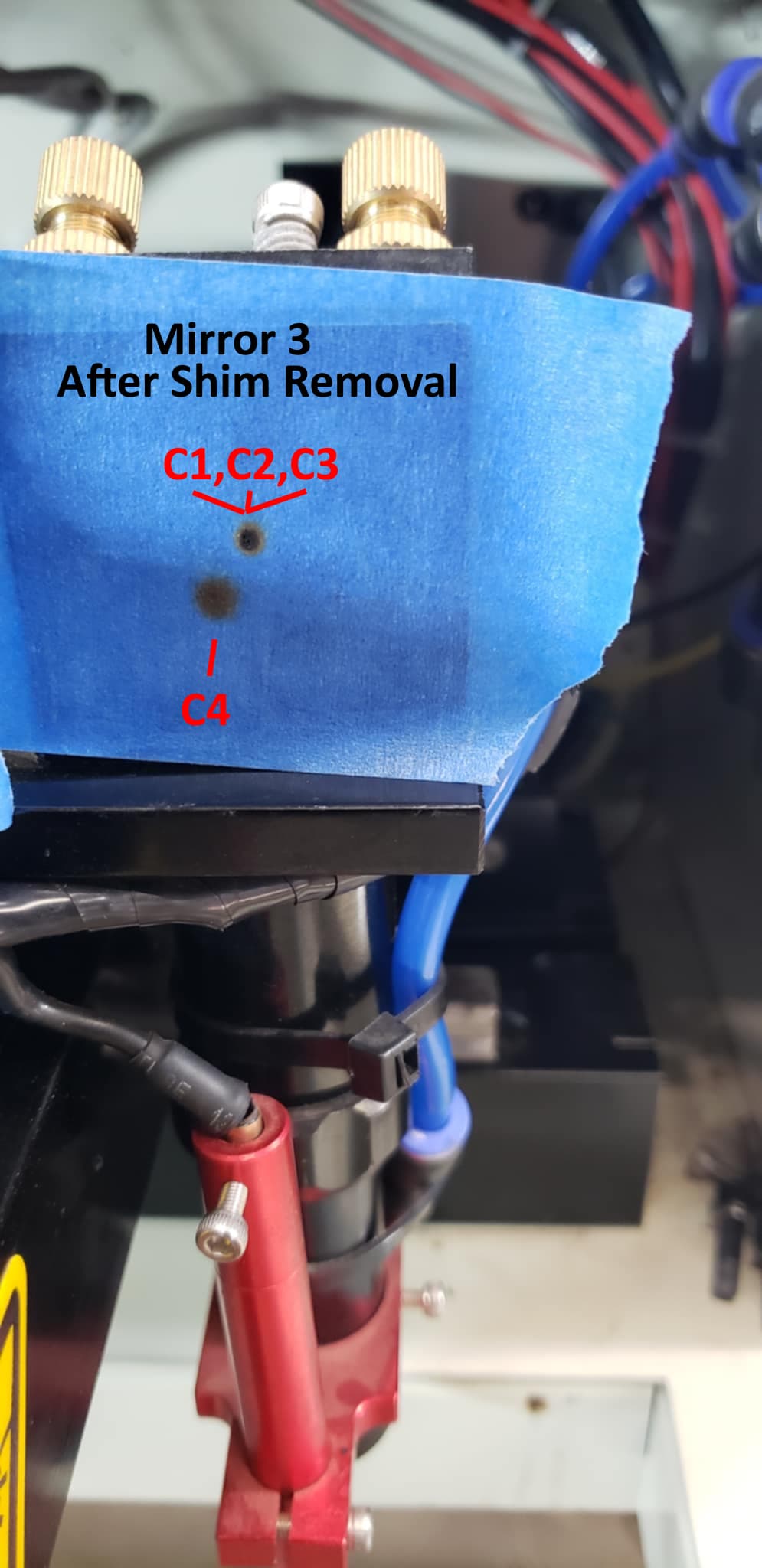
I put a piece of tape on M3 and drew a black line where the laser hit corners 1,2,3 (all perfectly aligned), I then measured 6mm down and drew another black line. I then lowered the leg underneath C4 down to where the bottom black line touched the laser. This now puts C4 6mm below C1,C2,C3. This was performed when the laser tube was set back to as coplanar with the gantry’s as I could make it.
My current hunch (completely unfounded) is that the left Y gantry that M2 rides on top of is twisting inwards as it goes down to C3. This could cause M2 to slightly aim downwards after it reaches C3. That could possibly explain why the beam drops 6mm in C4.
However, that doesn’t exactly explain why when C4 was lowered 6mm, the C4 burn is STILL 6mm below the other 3 burns.
So I have a few updates. I’ve tried a few new things but to still no avail.
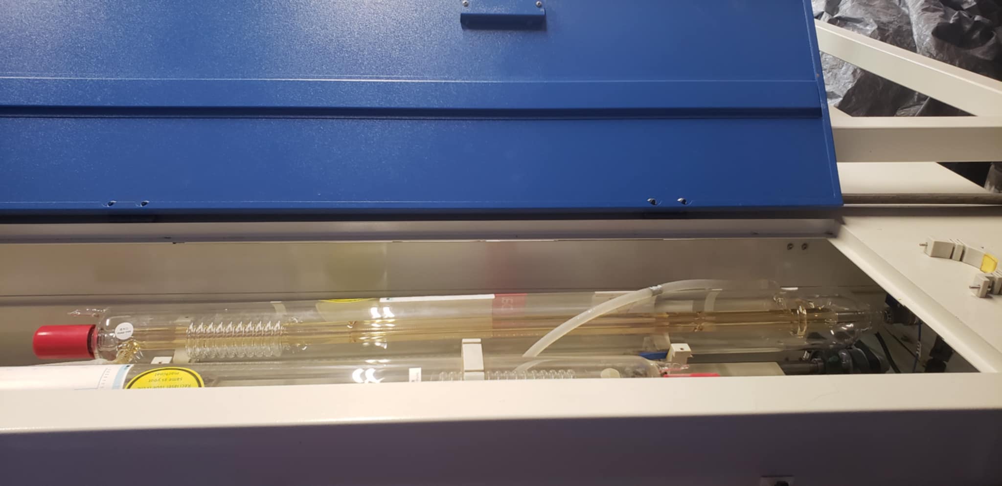
This machine has 2 laser tubes (1 lasers beam enters from the left side, the 2nd lasers beam enters from the right side). I tried to see if I could align the 2nd lasers beam and see if there was anymore information I could obtain about the situation. The 2nd lasers burn marks are very similar to the 1sts laser tube. The 4th corner burn is about 5mm down from concentric enter. This leads me to think the rail isn’t twisted inward as I had thought before.
The X gantry is not nearly rigid enough and bows down in the center of the machine. I actually resolved this by bolting on a metal bar with a lead screw in the center which forced the bend out of the gantry. This completely fixed the bend, but the non-concentric burns still persist. It looks crazy, but it works lol.
At least, compared to Ed and Jack, I’m not an expert in mirror alignment, but my attempt to summarize the situation might / or might not give a different perspective:
You can get centered marks on Mirror 3 in every corner except the front right (always 5mm lower).
You were able to align it to get centered marks on the front right corner, but then the back right mark is 5mm above the other burns.
Question: Can the whole assembly of the 3rd mirror be shifted up?
I removed a 8.42mm shim underneath C4 and the burn location didn’t move. I don’t understand how that works at all. But moving the mirrors/rails on the vertical plane (by means of removing shims or turning the lead screw feet that touch the ground don’t seem to have the desired effect were looking for )
I think this is what you were getting at. Please correct me if I’m wrong
I’ve come to better understand how to explain my problem possibly.
It is very difficult to align burns on M3 (Mirror 3) at C3/C4 (Corner3/Corner4). The only way I’m able to align burns on M3 at C3/C4 is if I crank M1 so hard that M2 at full distance is about about 5mm from concentric center of the rest of the burns.
So my real battle is to figure out why C3 and C4 aren’t aligning. The difference is purely on the vertical plane. The dots are in line, one above the other, but spread 5mm spread.
That’s a good idea to make it so M3 is co-planar at each corner using the 360deg level.
Try this approach if you haven’t already:
After aligning M1, and then M2 at the back end of the machine you will have C1 C2 C3 spots stacked.
Now burn the spot at C4
If it is low, while in that same position adjust M1 to tilt up ever so slightly until the new spot at M3 is the same distance above the other stacked spots as the spot at C4 was below.
The next time you check the alignment all 4 spots should be slightly higher, but hopefully (overall) closer together.
If the distance is 5mm between C3 and C4, 5mm higher than C3 might be too much…you will soon know I guess. It might make more sense to go “half the discrepancy” past instead, then test on a new tape, and repeat if needed.
So I was able to get in contact with Rus who was very kind to chat with me over video. We concluded that there must be a mechanical issue affecting M2 and the machine isn’t capable of having a coincidental burn in all 4 corners. Just is what it is I guess.
I’m really not surprised. I’ve spent way more time than any sane person ever would on trying to solve this problem and I was never able to.
 , he’s spent many hours helping me) I adjusted M1 to try and pull C4 burn closer to the other burns. This was unsuccessful and the best I was able to do was get C3 2.5mm above concentric center (C1) and C4 2.5mm below concentric center