Hello I’m new to electronics and I want to learn how to wire a power supply to a MKS DLC32 controller.
Hello I’m new to electronics and I want to learn how to wire a power supply to a MKS DLC32 controller.
Search for “k40 and MKS DLC32”, there are many guides that explain the wiring, I think. There are also different options you can use. I remembered having seen at least three or four different wiring options. If you search this forum, you might also find some of them.
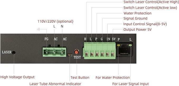
It’s relatively simple… Beside a common ground between the signals, there are two control pins on the lps…
P isn’t one, but you need to know it’s a protection input from your chiller that is active low. Not active, no lase…
Generally they connect the wiper of the pot to IN, then the PWM to H. When the PWM goes high it will lase at the set current level specified by the IN voltage.
I don’t favor this method, as it drives the tube like it’s a diode or a digital device, but it’s most common.
I prefer and I see more of this wiring … where the tube is driven, like it’s designed, as an analog device.
L being used as laser enable, with a manual switch to ground and the PWM going to the IN terminal.
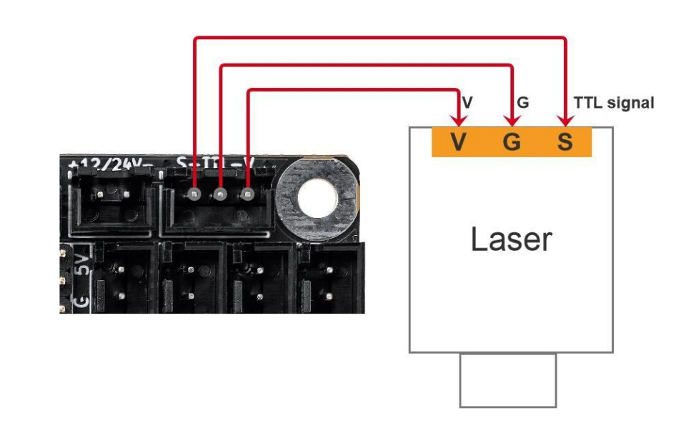
Note the connector has the PWM on S and the Ground on TTL in the center… it’s a ttl compatible output… There’s no need for the V (supply voltage) pin.
Pick your poison…
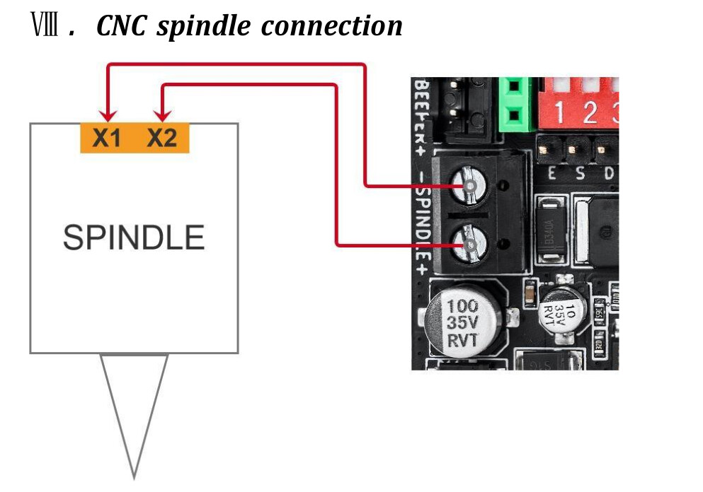
DO NOT use minus (-) on the spindle connection for ground, it isn’t. It is switched to ground by a mosfet when the pwm signal goes high.
Good luck
![]()
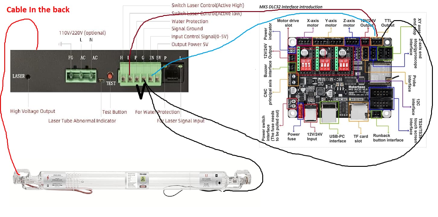
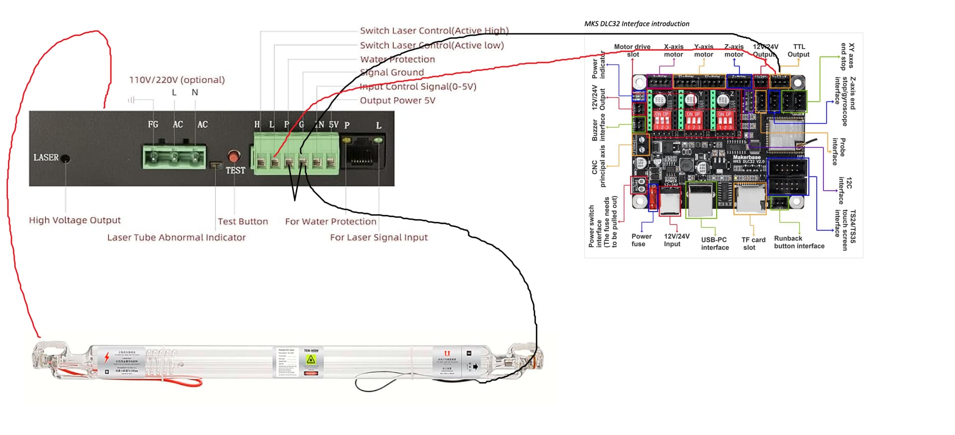
Hi jkwilborn, I really appreciate the information. I’ve been searching a while for a wiring guide and I have seen you pop up in multiple discussions and am very thankful to have someone so knowledgeable. Here is what I have ended up with for a wiring diagram from my still very beginner knowledge.
And I’m assuming that FG, AC, AC just hooks up to a three prong power cord?
If you look at the wiring I posted for the connector, I advised you have no need for the V output of the connector. This supplies voltage to the laser module, which you don’t have.
The center post is ground and the left is pwm… The right hand pin V, should not be used here, anywhere.
Might want to run the L input to a lase enable switch… any time the lps has power, it will have it’s laser enable active, so it can lase… This is commonly run through your switches that are for protection to prevent the lps from lasing when you don’t expect it.
Make sense?
![]()
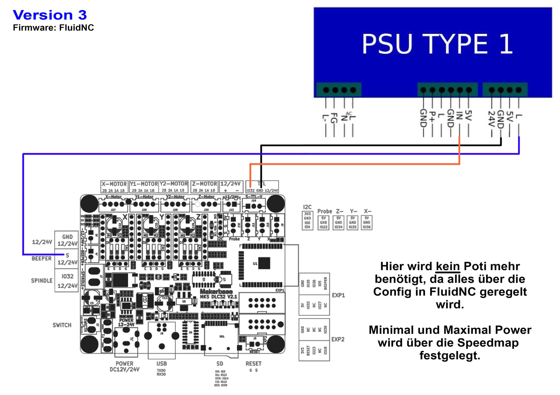
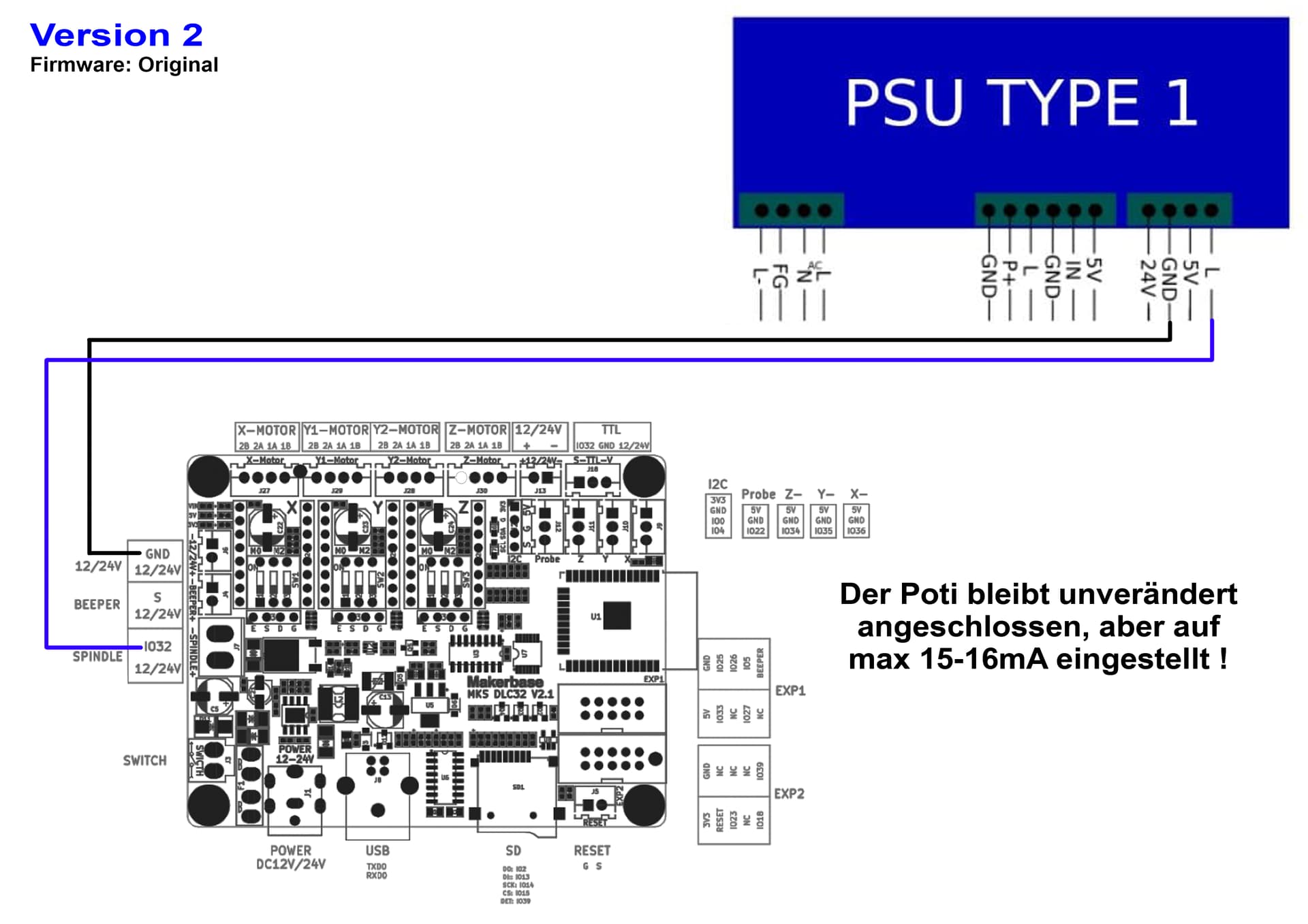
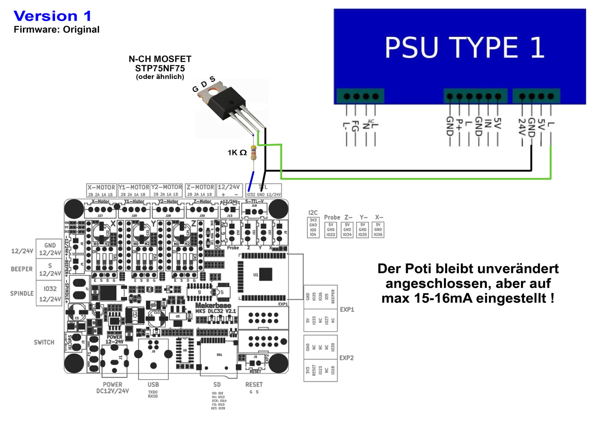
To increase confusion, here are some additional methods, taken from a German forum post, but maybe those help as well. Methods also depend on the firmware you use.
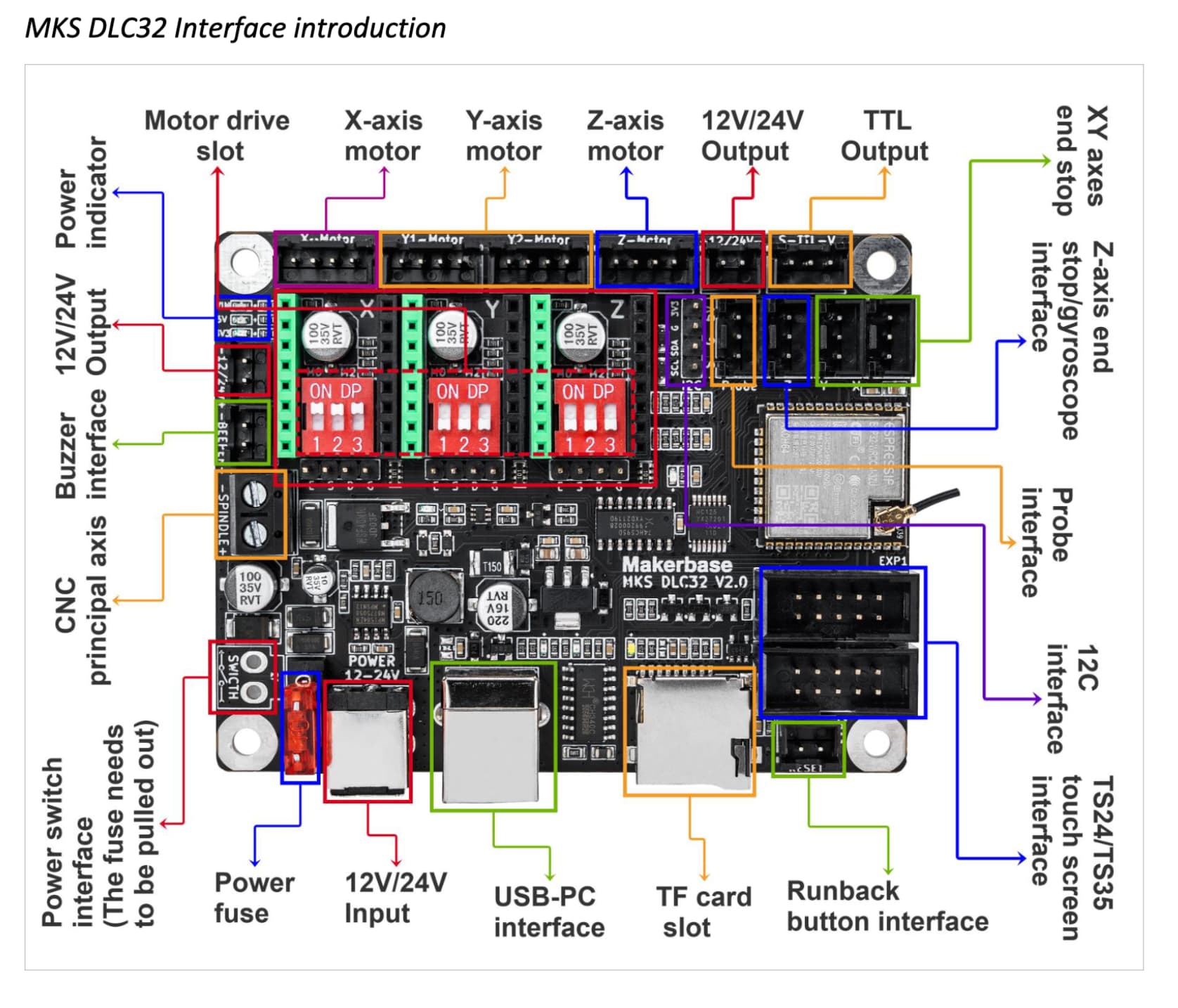
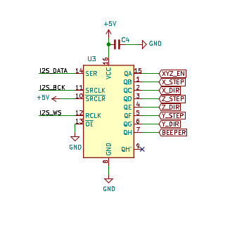
I believe the beeper output is J4
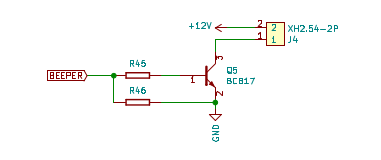
It’s driven off the stepper motor output chip…
I have no clue how this works, except it must be firmware driven and there is no mention of what it’s doing in the manual. Is your German good enough to tell us?
I’d like to know how this is determined by the firmware…
The proper way to control an lps for a analog glass tube is current via IN and Laser Enable via L (or H). If you drive L (H) with the pwm signal, it’s now being driven like a digital device.
In effect you now setting it to lase at the manually set lase current. Usually suggested as it’s maximum current.
The tube is capable of turning on at 50% power, unlike an ssl. The pwm turns the tube on at maximum power for a percentage of time, then turns it off… These are not digital devices… It’s a conversion to power/time, just like a ssl.
IMHO - take it for what it’s worth to you
I got my DLC32 board out and plugged it into the scope. The beeper output appears to be inverted pwm output. So it enables when the pwm goes high… wonder why they would do this…?
From what I can tell, it’s not doing what it needs to do… It’s turn it on and off, again like a digital device.
I have firmware version - laser software.
[VER:1.1.2022010501:]
[OPT:MPHSW]
[MSG:Using machine:MKS DLC32]
[MSG:No Wifi]
![]()
I revamped the wiring guide, I hope this is correct.
And when you mean “run the L input to a laser enable switch”, do you mean The ethernet port on the laser power supply? I have toggle switches, but how would I run an ethernet cable from the switch to the port?
Thank you once again.
Toggle Switches I Have: https://www.amazon.com/gp/product/B078KBC5VH/ref=ppx_yo_dt_b_search_asin_title?ie=UTF8&th=1
Many times people put protection switches to ensure the machine does lase when you don’t expect, such as door open or coolant flow…
Sometimes they are wired in series to P (water protection), so all switches must be closed to allow it to lase. You can do the same thing with L, it’s the laser enable, so if you go through a console switch to ground which enables the lps to lase the tube.
What do you plan to do with IN?
![]()
Well originally I thought the IN goes into the MKS DLC to control the laser turning on and off and it’s intensity. But in all honesty I have no idea what I’m doing. Are you suggesting I have an on and off switch for the lps? What is an lps as well?
LPS is the laser power supply…
What kind of machine do you have?
Your profile doesn’t tell me much…
![]()
I’m building my own custom laser cutter. I was following these videos.

")
Thanks… I’ve watched them both… I also noticed that Russ had made a comment or two.
Can’t say I agree with everything, but he has a pretty good creation… I didn’t see how he advised you connect to the lps…
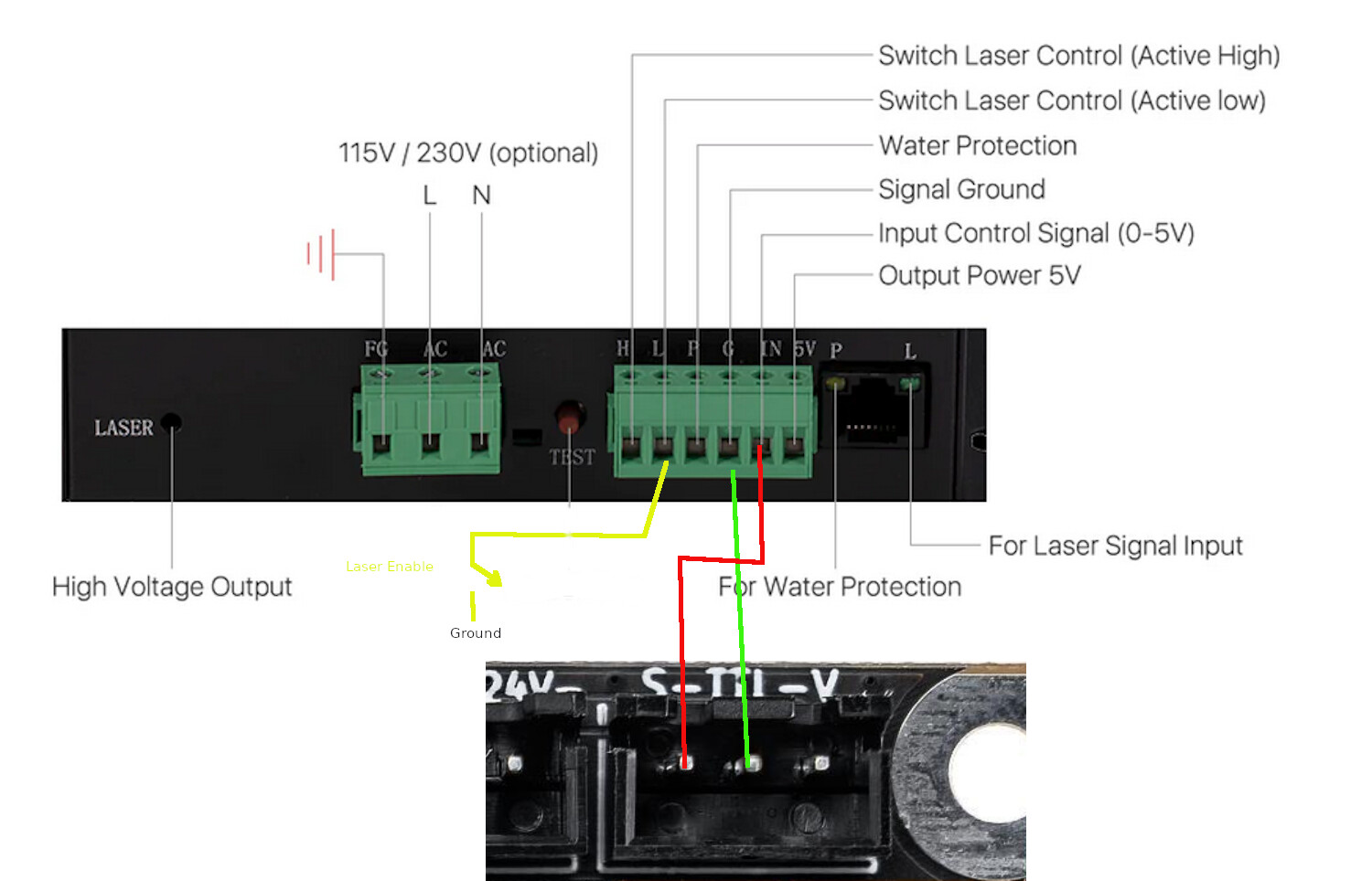
The lps is designed to limit the current it supplies, based on a 0 to 5V control voltage on the IN pin. The laser is enabled by the L input.
In your case, I’d suggest that the L input be a console switch that is manually enabled to pull the input low, enabling the lps. When you have any kind of voltage on the IN pin, it will lase at that current limit.
This is my suggestion…
Does this make more sense?
You have to deal with water protection input (P), if not at or pulled to a low level, it will prevent the lps from lasing. It has to be actively set at this level, if left unconnected it’s input is internally pulled up disabling the lps.
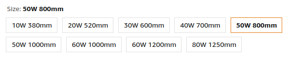
Don’t be mislead by some of these advertisements…
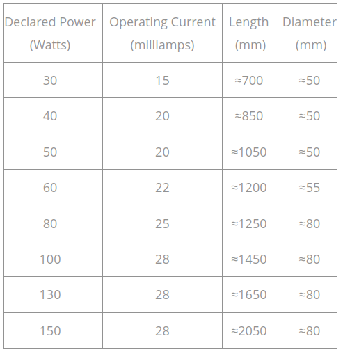
This tube is not a 50W tube. Physical size, usually length dictates output power. When you get to the higher power levels, the diameter increases from the 50mm range to the 80mm range, including length.
You should question any kind of data like this from an advertiser… 50W tube length is 800mm - 50W tube length is 1000mm … 60W tube length 1000mm, 60W tube length 1200mm?
The area between the mirrors, within the tube is where the Light Amplification occurs, part of the LASER, acronym for ‘light amplification by stimulated emission of radiation’ originates.
I’ve used this chart for the few years I’ve been doing this and, although a bit conservative, it’s actually seems very close.
My 50W China Blue I got from OMTech had an 880mm tube in it… It measured, with a Mahoney watt meter, 43W, which fits well with the chart.
A 50W tube needs to be about a meter in length, which won’t even fit in my cabinet…
There is a basic setup procedure to sync up your software so your percentage setting relate directly with current or wattage.
Coolant flow is important, and I’m surprised Russ didn’t mention it. The outlets for your tubes coolant need to be in the UP orientation, this naturally purges bubbles out of the system. My replacement tube has a big sticker this side up for this very reason.
When he tested it, although quick, it appears that there are areas in the tube that are not covered by coolant… Just ensure yours are…
It’s be nice if you posted your project… We all love diy …
Of course, you get to do what you want…
Have fun
![]()
I appreciate the great information. Thank you so much for the diagram as well.
I am still a little confused on the water protection input (P) because I saw in a video if you don’t have a water protection input (P) then you should hook it up to ground instead. However I am very open to adding one, would this require more parts?
Video In Reference: https://www.youtube.com/watch?app=desktop&v=pWvv7TFcK5Q&sttick=0
The W of the laser cutter might affect the project since my version of the laser cutter is going to be drastically bigger. The bed size will be about 5.5ftx5.5ft.
This is hardware protection. Like any kind of protection switch, you can wire it to the desired state. Or over ride the automation of protection.
On my machine, P is wired to ground, as my controller knows where it is and what it’s doing if something happens during a job… As far as I know, you can’t do this with a DLC32.
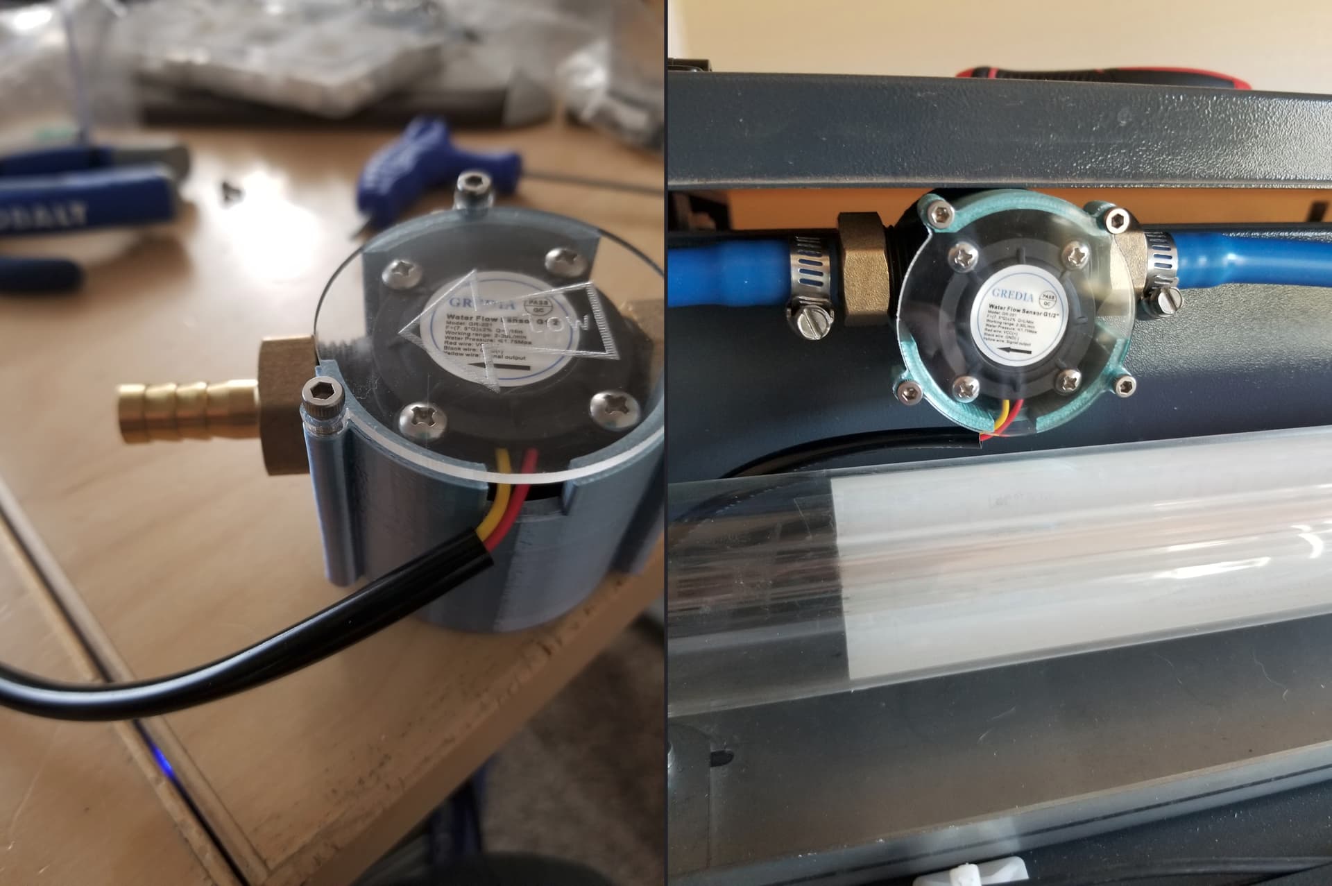
On machines like yours or K40 types, this is commonly wired to a pressure switch that operates when there is coolant flowing. Don’t buy a flow meter, per se, it needs to pull the P input down.
If you don’t install one of these you will, at some point you run it without coolant… your tube and machine are at risk without coolant flow.
The main idea here is for you to understand how these work.
It’s pretty large…
Good luck
![]()
Luckily I love to learn so any and all information is welcomed.
I found this switch, but I don’t know if it’s the same thing as what you recommended to not use flow meters.
https://www.amazon.com/Switch-Protect-Engraving-Cutting-Machine/dp/B07MS859HS
The switch in the link looks like it should work. A big tip off is that there are only two wires. Many sensors output pules based on flow rate require power, ground and signal…
This is actually a flow meter in mine, requires a little micro controller to figure out the flow rate. The chiller has a flow switch and temperature measurement system. So the chiller is wired to my controller.
You can’t see the black wire… but it has three wires.
![]()
I see and I’m assuming that micro controller determines if the flow rate is below a certain portion it will prompt the lps to stop.
The two system work totally different… Most flow meters have an impeller that rotates with the flow. That generally creates pulses, an external micro would have to count the pulses and determine how much is flowing.
Could it then notify the controller/lps, yes. But, usually, they use a simple switch, like you posted that closes when there is coolant flow, grounding P.
Keep this stuff simple… it’s designed for simple intefaces…
Good luck
![]()
I see. I’m going to order one as soon as I can. However in the meantime I worked on getting the stepper motors to work. However the x axis isn’t moving when I test it. I checked for continuity of the wire using a multimeter and it was all good. I don’t believe the controller itself is broken because I managed to get the x axis to work in the beginning.