$79 Cenoz laser engraver on Amazon... any good?

Jan, then you might be to get appropriate length cable, JST XH 3-pin on both ends. 3-pin can be easily plugged into 4-pin header.
Measure length carefully. I think you need about 4 feet. It goes through both chains, and you need a slack on both ends.

My LaserTree 20W came with spare cable. It is a larger (smaller gauge) wire but only 2 ft long, not enough to snake it through both chains. Then you need to unhook pins (easy to do with sewing needle) as chain is to small to feed wire with connector.

I’ve seeing some images where people do not bother to route fatter laser wire through chain. (I believe I’ve seeing Jakc’s setup and he also running point to point without chain, not sure though). Not my style but a possibility.

I would advice to learn to crimp. This is not a major investment and not difficult to master but makes life easier.
JL2 for example does not have chains at all, only plastic coil wire organizer, point to point.

I just checked pinout of laser head on JL1: Pin-for-pin 3-pin laser cable will need to be flipped on one end. Ground is in the middle, but power and PWM are on opposite sides. So even if you get straight through cable - one side need to be flipped. Or keys cutoff from the connector, but that would present big risk.

I am running the original you supplied. Have not tried much since I’ve had ‘life’ to deal with…

Have not tried the home function, I’ll have to move my Y switch and I can’t find any ‘t slot nuts’ that fit the JL1 frame, they appear to be 2 or 2.5mm thread…


The board is returned to it’s cabinet, so no access to the programmer header.

I did run a set of more ‘heavy’ wiring through the drag chain. The original wire is also there. I can swap back to the original head.

The board is there for an easy connection to the lps.

The ‘hack’ you saw before was just in the development test stages… I don’t like a rats nest either, which is why it’s back in it’s cabinet.


@JVL The pins in these connectors come out, with a sharp tool to push down the retaining clip… Pins on the board are soldered there…


The one I ordered came today, it’s still in it’s shipping box…

:smile_cat:

As many/most of you know I bought two of these machines… and I’m now setting up the second one. All is going well… flashing and configuring GRBL, wiring mods for different laser, etc. One thing I’m doing different, however, is adding a newer, thinner, Z-lift to minimize futher reduction of an already small workarea.

This machine really presents a nice big, flat, metal, carriage plate to work with and enough convenient pre-drilled/threaded holes to make it a “snap” to bolt stuff on…

Removing the included laser and red cross-LED module, I used Onshape to create and set up a relatively thin three-piece dovetail slide using the 3-hole “stack” down each side…

The central slide provides ample room for different laser module hole patterns. But I’ve got several Neje laser modules that came with a high quality metal clamping mechanism so I just added holes to mount one…

Setting the laser on it’s feet a simple clamp holds things quite securely for testing…

Noting the two large holes at top, I envisioned a bar with threaded bolt through it to clamp the slide in place. I found a printed C-clamp and a knurled thumbscrew out on Printables… and then used TinkerCad to cut, stretch, combine, and add the bits I needed to make a suitable clamp mechanism…

I’ll probably need to lengthen the central slide to insure I have enough “reach” to get down to the work surface but otherwise all this seems very workable. I usually set all my lasers to focus at 50mm below the bottom edge of the laser housing, so using a 50mm gauge block I can easily set the focus for varying material thickness…

I’ll put it out on Printables when I get the time and energy.

Wow, I’m tuckered… I think it’s time for my nap :thinking: :roll_eyes: :wink:

– David

3 Likes

I put “Another Z-lift mechanism for $79 Cenoz JL1 laser engraver from Amazon” on Printables for those interested. – David

3 Likes

Thanks… snagged it off Printables…

Thanks for the time and efforts along with making it available to all of us.

Take care

:smile_cat:

1 Like

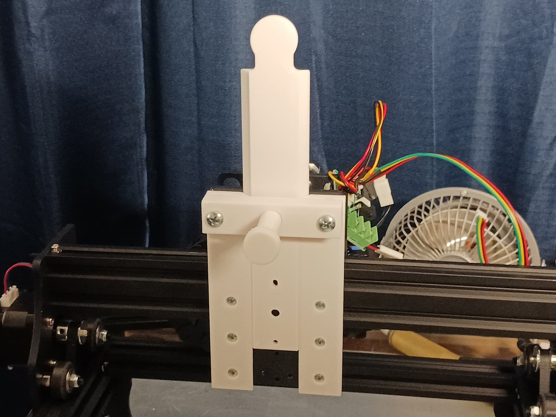
Nothing “ground-breaking”, here. Just a longer central slide on my latest Z-lift mechanism to allow for a longer “reach”… also has been added to Printables.

– David

1 Like

If anyone in the US has an JL1 board they are not using(ie maybe have replaced with another controller) I’d be willing to take it off your hands for the cost of shipping. PM me if interested.

This is so I could test grblHal builds on it. I’d like to leave my stock JL1 as is because eventually we’ll be trying to figure out the encoding and offsets so that a grblHAL firmware could bin installed with the stock update.exe updater instead of having to open, connect to ST-Link header and upload over the existing bootloader.

I have my second one ‘updated’ but haven’t opened it up. Works with lightburn this way, but haven’t done much with it.

It would be nice to be able to upgrade the firmware via the usb connector. Good luck with the chinese windows program. Do you know if the .bin file is ‘modified’ or the loader itself does something different? Seems to me the Windows program talks via some kind of encrypted link.

Have my hands full with a tiny85 for another project…

:smile_cat:

So do you guys have a simple firmware upgrade for working with LightBurn and has endstops?
I thought the only solution for non-programmer types was without endstops.

I personally have NO NEED for something which works with a Windows update utility over USB. My main goal is to get a version of a supported open source grbl firmware on the machine and I can do that with ST-Link programmer. So preserving the stock configuration/board is only for testing if someone hacks the encryption and offset address used in the stock bootloader.

I was hoping for a ‘generic’ type of upgrade via the usb. I only use windows when there is no other option and I have to steal my wifes machine to do that…

I run Ubuntu

:smile_cat:

Had you tried to see if DFU uploading works? From what Sal has said it seems the vendor put on their own bootloader which decrypts a firmware file and loads at some flash memory spot beyond the bootloader. Maybe they also have DFU capabilities…

Nothing will connect to the USB on the stock board, except the supplied software and the ‘upgrade’ program.

I tried to connect the ‘cube’ via USB before the upgrade and it didn’t see it.

Now that it’s upgraded it has this issue with UART mode.

dfu mode:

I followed the ‘cube’ instruction for connecting to the boot loader, but I got lost here:

I haven’t dealt with this to get into the factory bootloader… have you?

:smile_cat:

yes. there are Boot0 and Boot1 pins which have to be jumpered in order to upload firmware to the proper memory sections. I generally just use Boot0 for the firmware. Didn’t you have to do this when you blew up your bootloader and had to load manually with the ST-Link pins?

Possible, with the new one, I pressed the button then just uploaded it with st-link hardware… Not sure what happened with the original.

I don’t know for a fact what I did but erase the chip… that was pretty clear.

These bootloaders are done by the factory and are not erasable if I read the documents right…?

:smile_cat:

I’m not sure if the DFU loader is that low level. I can check by trying to use DFU with the UART/FTDI cable connected to the Bluepill board. Later tonight though.

I tried it with the button, but no different signs of life.

:smile_cat:

Doug,
Are you done with firmware? Got it all working? You still need to prune it to about 40K, maybe 50K-ish.
I’ve posted earlier that my x2 JL1 purchased at about same time in July, have different flash size, one is 64K and another is 128K. This is long known in Blue Pill world, that some 64K spec parts are actually 128K. This mean that target flash size must be 64K.

I perceive firmware vs. de-scrambling and using factory boot loader as two different efforts.

For Jack:

this is exactly what Doug now is talking about.
I think better code and firmware form Doug is just a matter of time.

De-scrambling is a bit of unknown. It can be super simple, or can be impossible. All depends. It appeared to me as simple but so far I have no idea how to scramble/descramble it.

Factory boot loader, as long as it is not erased or overwritten by STLink - will persist. I have tested it, flash JL3, then whatever else, then back and forth with various bin files - factory boot loader is safe. Feel free to boot into boot loader with button and flash whatever.

STLink however can easily overwrite it. Flashing with standard offset (beginning of the flash) will erase factory boot loader.

Without STLink or other special tool, most people using USB only, will have to live with factory boot loader. So, to use it, we should scramble BIN the same way. At this time the only thing loadable with factory boot loader is JL3 firmware. the good news is that apparently it is not possible to brick it f flashed only through USB (tested on board with 128K, I hope the same is true for 64K board).

Offset for factory firmware is easy to figure out. I’ve learned that flash can only be loaded in 1K chunks. Most boot loaders are 1-4 K. Worst case flash size minus firmware 64-40=24K (24 start addresses), left for boot loader. This is checkable manually, no special tools needed. Most likely will be some offset in full 1K iterations but no more that 8K. (I vaguely recall something that offset is full 1k plus 4 bytes, This info is mostly for Doug, please read about using bootloader+app code and offsets, I believe it is nK+4 or somersetting like that).

Clarification about boot and strapping boot pins:

  • STLink can flash the chip no matter what boot pins configuration is.

  • Both boot pins low => start form standard flash offset.

  • Boot0 high=> start form system memory, this is where factory (ST, not the JL1) boot code is. This is to flash though serial or other interfaces. I have to note that I have 5 year old Blue Pill that can be flashed over serial with Cube Prog as prescribed. JL1 board and latest lot of Blue Pills does not respond to serial connection by Cube. ST stated that they can program system memory to order, but user cannot change anything in system memory. I can speculate that these F103 have custom blanks in the system memory. Maybe somebody get better luck with ST factory boot loader. It is not difficult to jump Boot0 pin on JL1 board. It just appeared that it may or may not be the the option.

  • Boot1 will make chip to boot from specific offset in RAM. This is very specific use case and probably not for us.

  • It is not difficult to use command line utility and automate it with script. No need to be programmer, it can be made very simple. However still need 4-pin header and the dongle and driver for dongle installed (which did not install automatically on two ob my windows 10 PCs).

I’ve already posted samples form scrambled and unscrambled BINs. Collective help here can go long way.

Doug, I have two boards, one without boot loader, flashed with my own firmware. The other still have factory boot loader. I can test whatever you have.

Should we get new thread to work on boot loader scrambling?

This one is already unmanageable… you have my vote

:smile_cat:

it is working from I can tell, ie pwm works on PB0 and when I checked X and Y axis stepper pins they looked to be toggling with move commands. I have not relocated the motor and endstop pins yet. In a post to you I included a link to my repo once I got PB0 remapped and working.

That is what I looked at today and I was not able to shrink it down any from it’s 111K size. If I can not shrink grblHAL down below 64K then it might be a moot point going further with it for this project. Otherwise it would be only of use to anyone with a 128K version of the stm32f103 in the JL1.

There was alot of stuff you posted which I had turned away from when my first order for one of these JL1 machines was refused a few weeks after the order was placed. I did not expect them to show up again. Thanks for reiterating that these are a mixed back of worms and to cover all machines, 64K would be the target memory size to be dealing with. Ouch.

Exactly what I figured too. But I was hoping to have a supported grbl codebase to start from instead of something which has been stale for 2-4+ years. It was a lofty goal it seems.