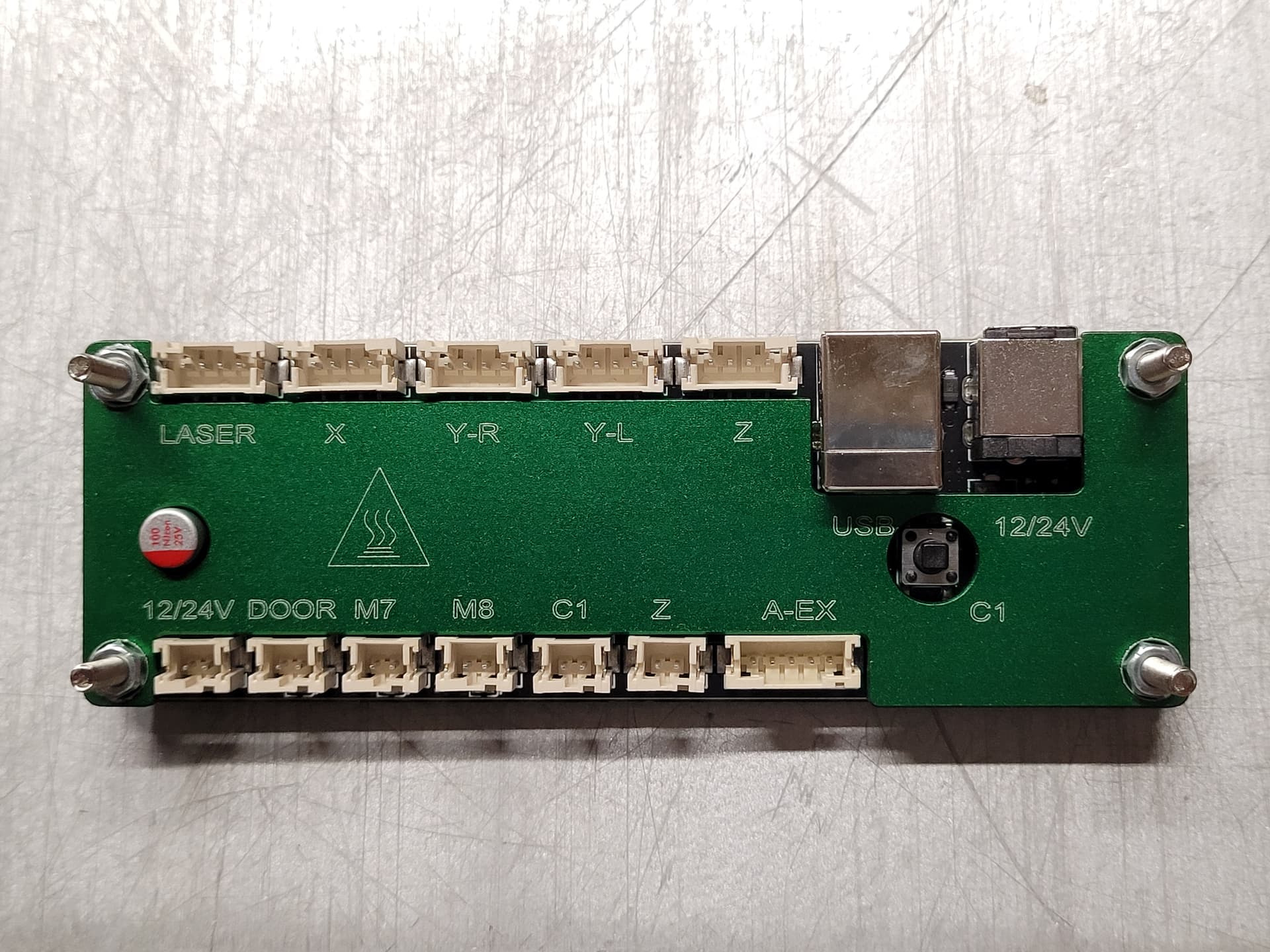
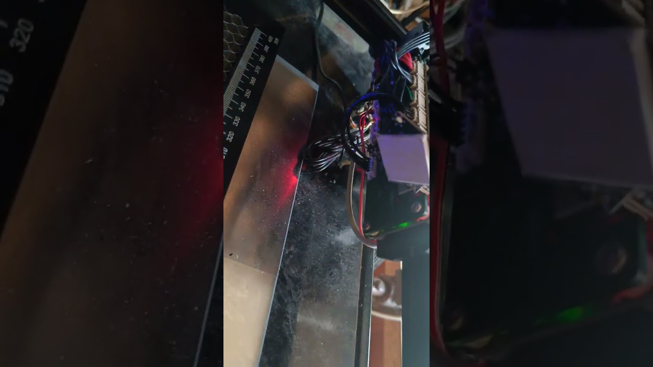
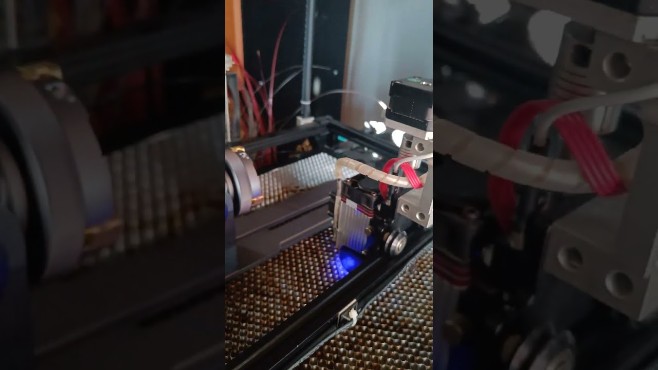
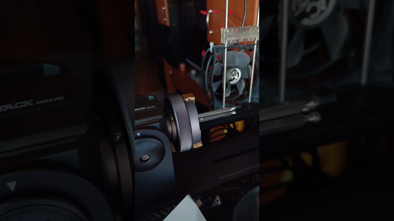
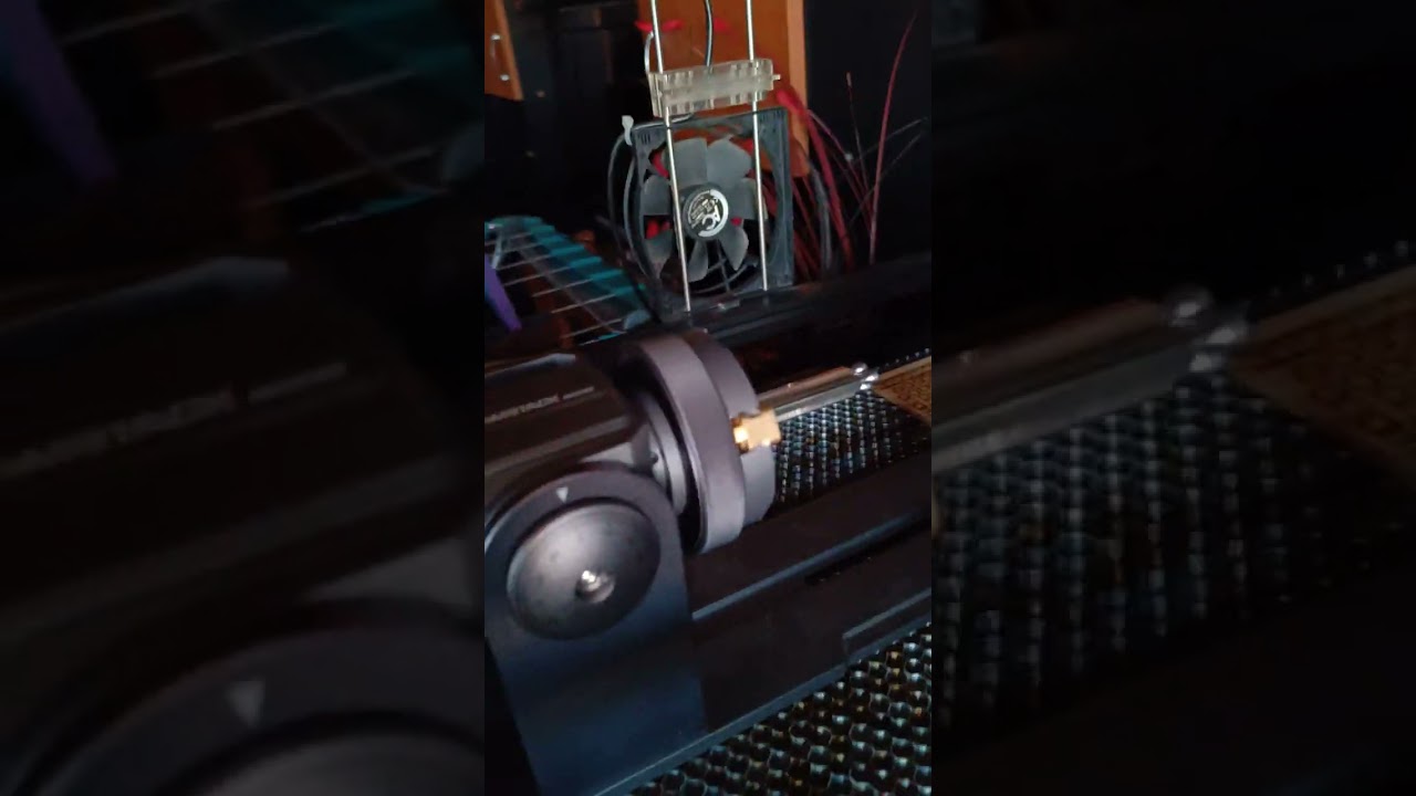
Hello, today I will also take the test proposed by you and I will let you know the results. Do you understand what my problem is? I have separate port for A axis.If I use A axis the execution time is extremely high compared to Y axis.I have attached a video. I contacted Neje support and they claim that the problem is from LB, I said that it is a GRBL problem and needs to be solved by Neje support because their board is not open source. I have attached a picture of my motherboard as well A-EX =A Axis port. Excuse my English.
I would prefer if you simply run the G94-XAF-test.nc.txt file. In the LB Laser window, click Run GCode button and select the file. Please post a video of the rotary motion as it runs. I’m interested in knowing or seeing the time it takes on the motion while “cutting” each of the 3 lines. By running this file already in gcode form generated by LB, all of the variables to affect speed are already baked in when it was generated. A final screen shot of the Console window with Show All enabled prior to run will show the gcode that ran.
However…
2) Since you chose to open the .lbrn2 file and run a new stream of gcode, it appears some of your shape/run pre-conditions were wrong, such as:
a) at 0 second mark of your video you used a cylinder diameter of 50mm rather than a cylinder circumference of 50mm which I mention in my post and planned for the test. The circumference is important in determining cylinder surface speed of the motion.
b) only 1 of 3 lines were selected (the X axis line) at 5 second mark of video rather than all 3 lines.
c) at 10 second mark of video you change the selection it appears to the vertical (180 degree) line since the width of selection changes from 50mm to 0 and the height from 0 to 50mm. Again, this is just 1 of 3 lines that should have been selected and run.
c) at 18 second mark of video some sort of controller parameter window is shown and I don’t know what to make of it, it seemed to contradict some pre-conditions but I can’t be sure.
d) at 19 second mark of video the LB work space grid very briefly shows the 180 degree vertical (rotary axis) line selected, but again only 1 of 3, and this line by the way will exhibit correct motion speed regardless of your grbl having the bug or not.
e) the rotary motion confirms the wrong circumference was used.
f) I don’t know the value of Start From field, job origin, Optimization, etc.
Net: I provided the .lbrn2 file just for reference. Let’s run the test using the gcode file please. Thanks.
However, the bad news is that it confirms that your Neje machine has the G94G1XAF feedrate bug; which is assigning the feedrate incorrectly to the A axis rather than the linear axis X, thus the coordinated move of XA is slower in this case, 22 seconds vs. 3 seconds for a 50mm surface distance of travel. There will be times when its slower, faster, and just right. If the cylinder circumference is 360mm, then the bug is masked and the surface speed is correct. The further the circumference deviates from 360mm and the greater the angle of XA motion from horizontal (A axis zero rotation), then the greater the actual feedrate will vary from desired/programmed.
I suggest you send the .nc.txt file to Neje and have them run it to make your case re. the bug.
Mr. JackWong is the one who knows my problem in detail and the one who put up with my endless questions. If you can give him details and suggestions to solve this problem please do it. This shows professionalism and communication and that’s the only way we solve the small problems that arise in our hobbies. Thanks to everyone involved in these problems, not only my problem.Excuse my English if I made a mistake.
It appears Mr @JackWong is already in progress of a fix, but if not, the grblHAL link earlier in this thread and the test case here should be all that he needs.
@mada recall the rotary speed limit on your machine, 250deg/sec, and how that translates into surface feedrate maximum based on cylinder circumference. See the math that Oz @LightBurn described earlier in this thread.
I’m not sure I understand your question? The linear feedrate in my 50mm test case is 1000mm/m or 16.7mm/sec, hence the 3 sec cut/traverse time. The cylinder circumference is 50mm, thus your machine can easily drive the rotary 360 deg in 3 sec.
However, at a linear feedrate of 150mm/sec, it only takes 0.33 sec to go 50mm (ignoring acceleration). With no change to cylinder circumference, your machine can not drive the rotary that fast, 50mm of cylinder surface distance is 360deg in this test, that speed is equal to 1080deg/sec.