I’m trying to find a little more detail on overscanning than I’ve been able to dig up through searching. I’ve attached a pic for reference, but first a little about my machine. It’s a custom built 90W CO2 machine with a Cohesion3D LaserBoard running the latest Smoothieware with clustering downloaded from the Cohesion3D site. The mechanics suck such that I’ve greatly reduced the acceleration and I scan at 90 degrees to overcome machine issues. I also PWM the LPSU control input for power regulation and switch the output on and off via the LPSU TTL pin. This is not the standard configuration for a C3D LaserBoard. The PWM’ed voltage goes through a trimpot to set the maximum current available to the tube in series with a regular pot to give manual control over the power level. All that being said I’m happy that I’m at a point that I can consider a good baseline for fixing all the various issues that are still on my to-do list.
I’ve done a lot of testing as I’ve built the machine to get me to this point and I’m just looking for a little additional info so I can do more testing without so much complete guesswork, (and scrapped material). Here’s the result of a power level test that I did earlier today:
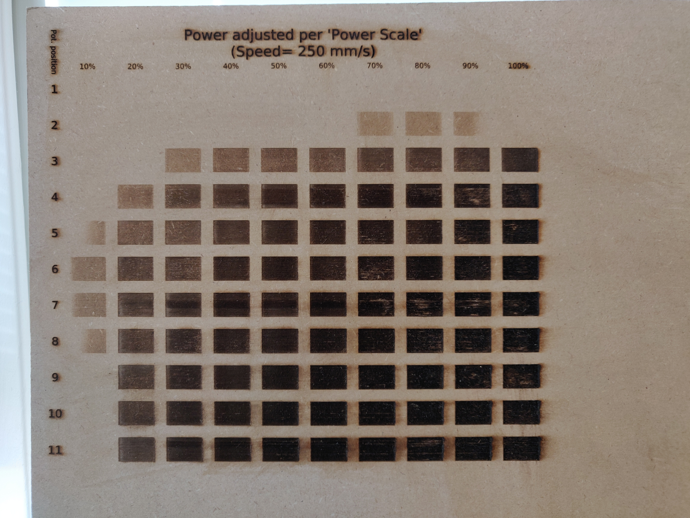
Each row is identical with the exception of being on a different layer so that I can run one at a time. The image is rotated 90 degrees, i.e. top to bottom as you look at it is the X-axis and left to right the Y-axis. As I mentioned I’m scanning at 90 degrees, i.e. in the direction of the Y-axis. I have overscanning set to 2.5%, and as a reminder the mechanics suck so that in this test I have acceleration set to just 500mm/s^2. Speed is set to 250mm/s, but I’ve no idea if I’m reaching that. That’s not really an issue for testing though, a consistent baseline is what I was aiming for. Between scanning each row I adjust the potentiometer from 1 through to 11. Row 1 is obviously blank because it’s too low of a power setting to do anything. Things start to happen at row 2.
So finally on to my questions. 
Row 2 starts to peter out at 90% which I’m presuming is because of the low acceleration. How does LightBurn actually scan a line, (or more properly produce the G-code for it)? It can’t know the acceleration setting of the particular machine (can it?) so does it simply start reducing power at some point before the end of the line to allow for some assumed deceleration prior to a direction change? If you greatly exaggerate overscanning would the power remain constant to the end of the scan line assuming the speed remained constant across the scan, (decelerrating entirely in the overscan)?
EDIT: For the above paragraph, it’s the Smoothieware firmware that actually changes the power vs. the acceleration/speed, and not LightBurn, right? But exaggerating overscan as suggested would have the effect I described? Still confused about the stuff below.
That would all make sense to me, but lines 7 to 11 start to fade at the beginning of the line even though the power is supposedly increasing. Now it’s entirely possible (and probably likely) that this is being caused by machine/controller/LPSU/configuration setup outside of LightBurn’s control, but because I don’t understand exactly what the process is I’m having a hard time wrapping my head around what’s going on. I’m looking for a little more than “use more overscan for lower accelerations”. Using the identical test file and upping the overscanning and acceleration are certainly going to be the next two things I try, but I’m still looking for a clearer explanation of what’s going on.
The other problem I’m seeing in this test I’m sure I’ve seen mentioned before. There’s a horizontal band in rows 7 and 11 that can most clearly been seen in the 30% column. It looks to be the same width but in a different position. Any idea what might cause this artifact? Again, just looking for some direction so I can do more testing without complete guesswork.
If you’ve got this far I thank you for your patience!
Here’s the test file for completeness:
Power_Test.lbrn2 (79.4 KB)


