I’m new to Lightburn and am now trying to familiarize myself with it for use with a Ruida controlled G·Weike Cloud 50W CO² Laser - As such I’m still on Lightburn 1.3.01 Trial ( mentioning it in case it matters ) with a bunch of questions having popped up:
Layers
In most Tutorials C01 Blue seems to be commonly used for Engraving whereas C02 Red appears to be used for Cutting.
Looking at how I can change their settings ( which all seem to be the same at the start ) though this appears to be a purely User Defined Choice - Not some kind of Industry Standard? The three Colors that appear to be different from that aspect appear to be C00 Black having fixed values and the two T1/2 with limited Settings - What’s their story?
Libraries
Having dabbled into the Libraries Function it first seemed to be an interesting idea to permanently ( Make Default ) assigning Material Profiles to the Layer Colors but the longer I thought about the less sense it made as with an increasingly growing Material Library the amount of available Layer Colors would quickly run out as such adopting the habit of assigning unedited Layer Colors to the Components in a Project which then get the Material Profiles assigned to them seems to be the way to go?
Fill+Line One of the Videos I’ve watched discusses the Fill+Line Mode in great detail when it comes to getting better Engraving results, but I don’t seem to have it in my 1.3.01 Version of Lightburn while his 1.1.04 does - Was this feature moved to somewhere else?
All I have is Line, Fill and Offset Fill
LightBurn is largely user configurable, this also applies to layer properties. You decide for yourself which color and property you want to assign to your layers, you can save the values permanently or change them for each of your projects. LightBurn actually also has a very useful and nice online manual, here I found e.g. this Overview - LightBurn Software Documentation
Some of the videos on the web that deal with LightBurn are made for older versions, i.e. they were current at the time they were made.
Fill+Line has been replaced with sub-layers, a good instructional video is here https://youtu.be/lLp1dvEkOlw.
I use material library in a different way. I have assigned certain colors to certain functions, so like red I always use as my cut layer, blue for text, black for engraving…and so on.
To cut 3mm acrylic, I have defined the red layer (my cut layer) with the corresponding values. For 6mm acrylic I also use red to cut with, but the properties/values are adapted to this thickness and saved for 6mm acrylic in my material library. A project, assigned a layer from the material library, stores these values in the project file. It works fine for me, I don’t use many different layers / layer colors on a daily basis. For wood and other materials I use the same system, so I always know which layer needs to be cut or engraved when I pick up an existing project.
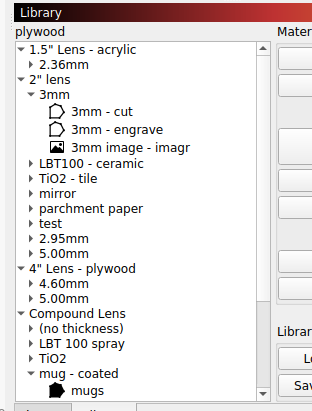
I’ve found that different lenses require different parameters so my library shows lenses at the top then the sub menu has thickness or material and what the operation is.
I don’t worry about layer colors. When I need to do something like cut 3mm basswood with a 2" lens, I select it from the library and assign/link it to that layer… no question about what that layer will do.
Biggest concern with layer color is ‘can I see it’ while I’m working on it… Some of the layer colors are not easy for my old eyes to see.
Works for me and handles the different lenses and applications I’m doing…
So, I spent the better of the past few hours since opening this Thread with trying to figure out how the machine works and have now come to the conclusion that before starting any work on Libraries I’d need to sort out how the Machine and Lightburn translate the Z-Axis Control because something doesn’t seem to be quite right.
@bernd.dk That 2nd Link with the Sub-Layers was helpful! Thanks a lot! @jkwilborn Yeaa… I’m not yet there when it comes to using different Lenses
Which Ruida controller is in your machine… I have a 6442g.
Lightburn is pretty much 2d has limited Z axes control as the controller is limited … apparently this varies with controllers such as a 6442 and a 6445…
I don’t have anything on my Z/U axes… so not much useful information from me about that.
AFAICT, if you set the focus at the platform surface, then the Thickness field in the Material Library will lower the platform (increase the Z distance) to put the focus at the surface of the material. For production work with many different materials and lightly skilled operators, automating the focus operation makes a lot of sense.
I just disable the Z axis, set the focus at or just below the surface, and away it goes.
Soo… Coming back to my “Issue” I finally managed to confirm my suspicion with something being off how the Machine handles the Z-Axis…
G·Weike - in their Manual and YouTube Videos - has you perform a weird Calculation of 17mm Focus DistanceminusMaterial Thickness and use the resulting Value to lower a homed Tool Head to the appropriate height for the Project instead of simply using the Material Thickness by itself.
I kept playing around with all sorts of settings I could find in the Machine Settings, Device Settings, etc… but couldn’t get it to work so I finally started wondering what the actual Problem is instead of just finding a Solution:
The Machine’s Z-Axis operates in the wrong direction!
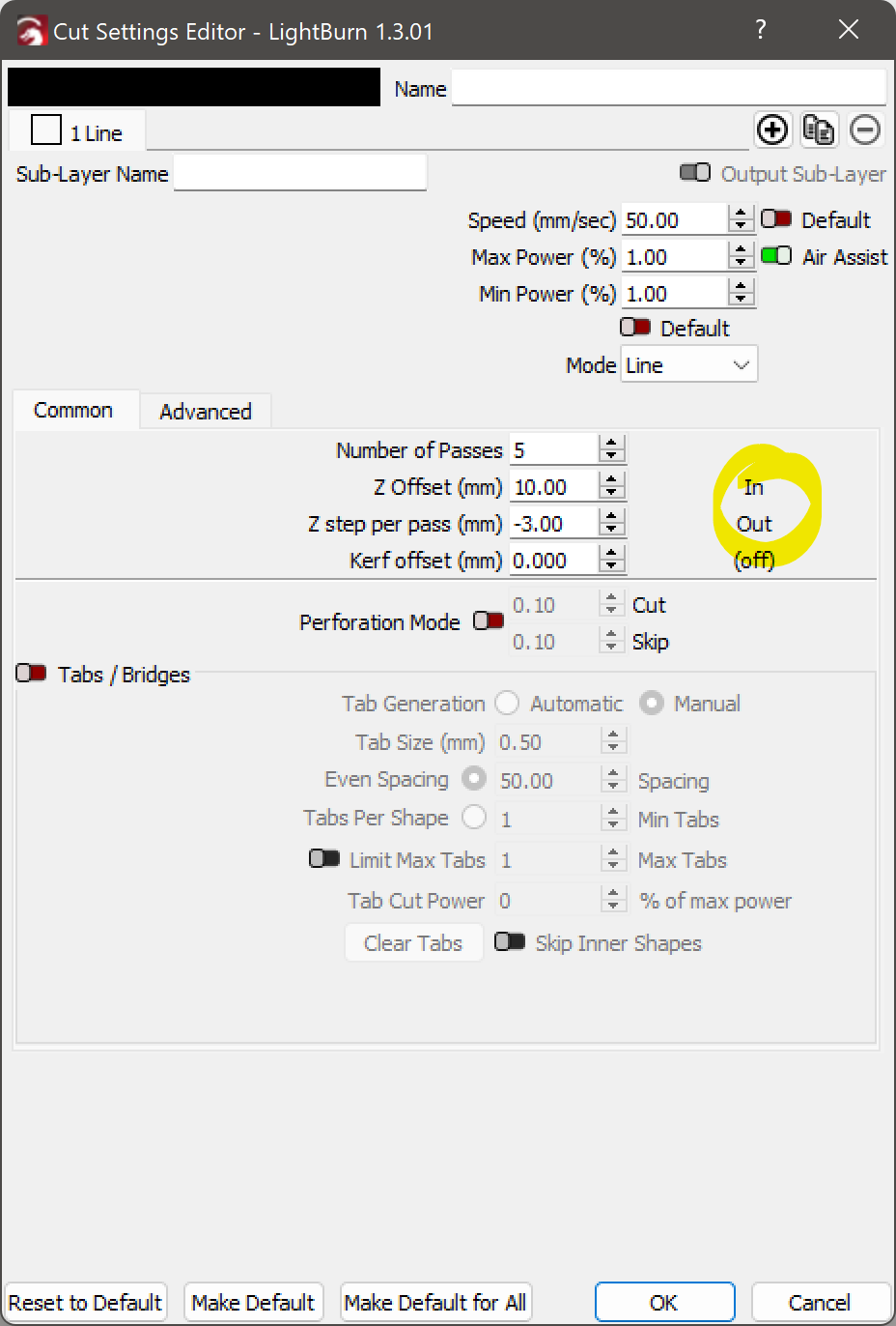
Obviously with only 1 Pass I wouldn’t notice it but when I created a 15mm / 5 Passes Material Thickness Preset and had the Machine perform imaginary Cuts @ 1% Power the Machine dropped the Tool to almost touching the Honeycomb Bed, made the first Cut, RAISED the Tool Head a bit, made the second Cut, RAISED the Tool Head again, etc… Yea mate that’s not how this is supposed to work?!
Anyone know how this can be fixed?
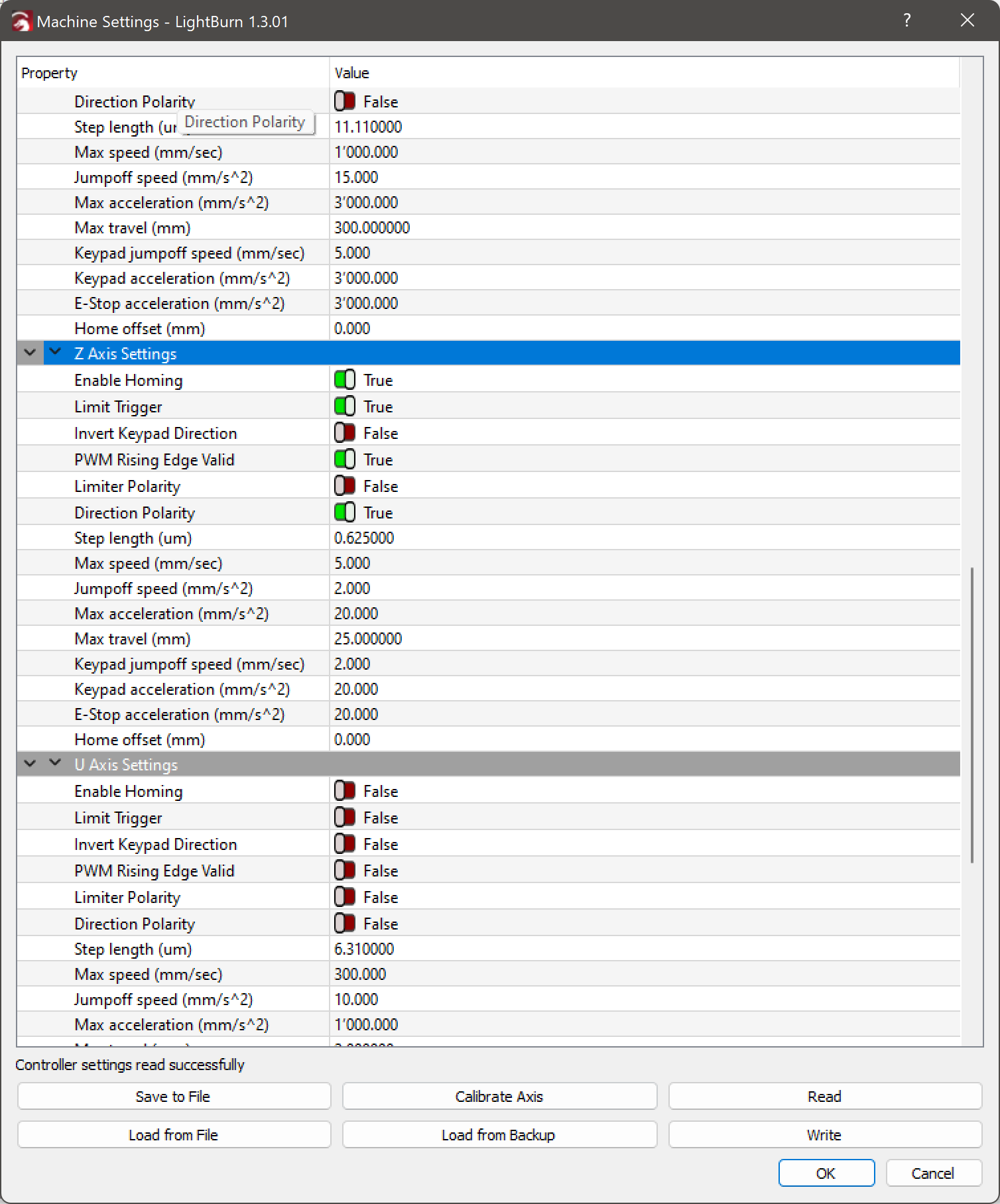
Maybe with a setting in the Machine Settings - Machine Vendor related Z Axis Settings?
Flip Direction Polarity to False and it’ll move the other way.
The problem comes from whether the platform moves (as in my OMTech CO₂) or the laser moves (as in most diode / CNC conversions). For my laser, “down” increases the distance and “up” decreases it. For your laser, it’s the other way around.
Which is why those configuration options exist, even if the defaults work out OK most of the time.
Mhh… Only flipping the Direction Polarity would indeed have the Tool Head now properly cut from top to bottom as opposed from bottom to top but at the same time it would introduce the problem of the Tool Head now moving away from the Switch when doing the Homing Sequence - It would stop after what I assume to be the defined 25mm of Travel Distance and while not reaching the Homing Switch wouldn’t lock up the Machine it would essentially mean it not knowing the location of the Tool Head.
If you think about a home operation, the machine could be at it’s maximum distance from it’s origin. When it homes from there is must travel for that maximum axes length to ensure it will touch a home sensor. Once it touches the sensor, it will backoff a few mm, I think mine is around 2.5mm. It has to hit a sensor before it can use the backoff distance for an error.
If you have it going the wrong direction (away from sensor) and it’s close to that end, it will hammer the whatever axes on the end with no sensor… until the maximum length of that axes is reached …
Absolutely. I can generally hear mine when it misses a steps as mine sometimes is running on the edge.
It will sometimes just lose steps, never has happened in a job but < 1/2 dozen times I’ve lost steps when it’s going back to an origin after a job… Happens so rarely and I don’t know how to troubleshoot an intermittent like this effectively.
The most effective troubleshooting starts with understanding how it works and that your need to sit down and about it, generally somewhere away from the machine…
( which quite honestly I’d do best reducing once I’m finished with solving this problem as clearly 25mm is too much as it enables the Tool Head to contact the Honeycomb Bed )
Will have a look tomorrow as it is now too late to turn on the machine again for testing.
But just to make sure… RIGHT NOW ( before making the suggested change ) the Laser:
DOES move in the right direction when I MANUALLY move it using the Controls found in the Lightburn Move Tab ( Up = Up / Down = Down ).
DOES move in the right direction TOWARDS the Material and proper Focus Distance IF the Operation has only 1 Pass OR multiple Passes WITHOUT Z Step Per Pass enabled.
Taking the current state of affairs into consideration with what I’m about to change ( inverting the Keypad Direction ):
I’m at least expecting the Manual Controls to end up being wrong ( Up = Down / Down = Up ) which is not much of a concern to me as IF it solves my problem then I’ll not have to make use of the Manual Controls anyway with the Machine then doing it properly - automatically.
In case inverting the Keypad Direction screws up with the distance how close the Tool Head will move to the Material - Which Setting would most likely help with adjusting it back to working condition?
The Focus Distance found under the Machine Settings > Miscellaneous?:
It may be a matter of definitions and the consistency thereof.
Earlier you had said “The Machine’s Z-Axis operates in the wrong direction!”, so I had (erroneously) suggested flipping the Direction Polarity control to reverse it, which made it move in the other (wrong) direction when homing.
Knowing that, I suggested restoring Direction Polarity for the correct homing direction, then flipping Invert Keypad Direction reverse both the keypad and LightBurn directions.
If that does not sort the directions out the way you want, then it’s not clear how to proceed.
The Focus Distance parameter determines how far the U (or Z) axis moves from its default position after the focus pen / switch trips: it adds distance and can only be positive. Mine arrived at 0.0 mm and remains that way.
That default position comes from the U (or Z) axis parameter Home Offset controlling the backoff distance from the switch trip point. Mine is at 10.1 mm, which positions the nozzle 18.5 mm from the material and puts the focal point at the surface.
I think the intent is to have the vendor determine Home Offset to make the focus switch work correctly with a minimum mechanical backoff, then add Focus Distance to match the actual lens focal distance. The settings on my machine came from OMTech, but I don’t regard them as unalterably correct.
How all those settings interact with LightBurn’s Z (or U) axis controls, I have absolutely no clue.
I’m not putting any blame towards your suggestion as it did change how the Machines would perform a Multiple Passes WITH Z Step per Pass enabled Cut to how one would expect for such an operation to work - Starting the first Cut at the Top of the Material followed by LOWERING the Tool Head for the consecutive Cuts - As such I’d argue that the Machine is - essentially and for the sake of productivity - operating inverted.
The machine - from a logical standpoint - behaving differently depending on weather it is being Joggged ( where UP = UP / DOWN = DOWN ) vs. it doing Multiple Z-Step per Pass enabled Cuts ( starting the first Cut at the lowest point followed by RAISING the Tool Head for the consecutive Cuts ) is confusing as Hell and the longer I think about it the more I believe it actually being a problem in Lightburn and not the Machine itself.
The Problem MAY originate from the Machine with the location of the referencing Z-Axis Homing Switch being situated at the top of the Z-Axis Travel ( being the case for 99% of the Machines out there ) but having a simple option in Lightburn to Invert Z Step per Pass order would immediately solve the issue ( maybe also include a setting for defining the Distance between the top of the Honeycomb Bed and the Z-Axis Homing Switch location to negate the need for a Material Thickness Measuring Probe? )
So did mine - I just updated it to 17mm in hopes of it potentially being the solution to the problem which clearly it isn’t.
Changing it to 17mm and manually hitting the [ + ] Z Focus Button in the Lightburn Move Tab will have the Tool Head move down to what seems to be the right Focus Distance. G·Weike seems to have left it at 0 as a means for the User to be able to conveniently returning the Tool Head to its topmost location as Homing the he Machine from the Lightburn Move Tab seems to only be homing the X an Y Axis which quite frankly I’m also having issues with… Why not include the Z-Axis in the Homing Routine with it being raised first followed by the X and Y Axis?
Being able of defining a NEGATIVE value for the Z Step per Pass (mm)is apparently a thing and IMHO something that would benefit from an Invert Toggle Switch being used instead more clearly hinting at the possibility
Setting the Z Offset (mm) accounts for the starting height of the Cut - The 10mm I entered are just a placeholder to prevent the Nozzle from crashing into the Honeycomb Bed until I’ve figured out the proper Value.
Needless to say, I’m not exactly agreeing with the location of the solution as I consider it to be an as inconvenient as can per Material Profile one instead of a global Machine one - In particular the negative Z Step per Pass (mm) one which… Like… Who cuts only some of their materials from Bottom to Top?!
I DO understand the need for a per Material Profile need for the Z Offset (mm) ( its Tooltip explaining the need ) but IMHO there should still be a Global one first with the per Material then adding or subtracting to that.
For my Sherline CNC mill, jogging “up” increases the distance between the tool and the table by raising the spindle.
For my MakerGear M2 3D printer, jogging “up” increases the distance between the nozzle and the platform by lowering the platform.
In both cases, the “up” button corresponds to an increasing distance.
I think the idea behind the Ruida’s setup parameters is to put the just-homed Z axis origin at the platform surface, with the jog buttons (and LightBurn’s motions) then raising the focus point to the surface of the material by lowering the platform: positive numbers increase the distance.
With that in mind, picking the Invert keypad direction setting so that the up button makes the platform go down is correct: it increases the distance from the initial home position. That should also make positive Z steps increase the distance (away from the work) and negative steps decrease it (into the work), which seems sensible.
So I think it’s operating as intended and you’re upside-down.