Hi
I’m using 0.9.16. Found something odd when doing print and cut. Seemed to have a weird mismatch between my first pass, which does some engraving and places 2 diagonal corner fiduchels, and the second pass that uses the 2 fids to align some cutting. The job comes off the laser in between the two passes, hence the p&c to align the second pass to the first.
Anyway, assumed it was me or the machine but after several hours of experiments I’m now not so sure. If I do the following test I get odd results (BTW the axes are fully calibrated and can render a 500mmx300mm rectangle to within 0.1mm or 0.2mm size accuracy, all nice and square etc and for this experiment I have no absolute use of the red dot pointer (other than to roughly eyeball where the head is relative to the previous marks I just made):
Create two crosses at 2 diagonal corners of an approx 500x300 rectangle
Create one cross right in the middle of this space
Set absolute coordinates and position the graphics to be roughly in the middle of the working area
Let it run, marking onto a large sheet of paper
If renders in what looks like the right place (approx by eye)
Once finished, use the click-to-move tool with respect the drawing/graphics…
Zoom in on each of the 3 crosses one at a time and click the exact middle.
Laser pointer shows various X offsets to the the cross (es) ranging from about -1.3mm through to about +1mm. Seemingly no Y errors though.
The most accurate alignment seems to be the cross furthest from 0,0 (that being top left btw)
So straight after marking out the paper, using the click-to-move tool, the revisited positions do not match what’s on the screen. If I run the job a second time…bang on top of the first pass. But again, click-to-move seems to have a different idea of where things are. So nothing to so with p&c but may be the root cause of what started this.
Help please. Is it me ?
(NB: I have no offset dialed in in the settings for the laser pointer…my pointer is in-path type not parallel to head type so no need)
More info, this time related to the original print & cut.
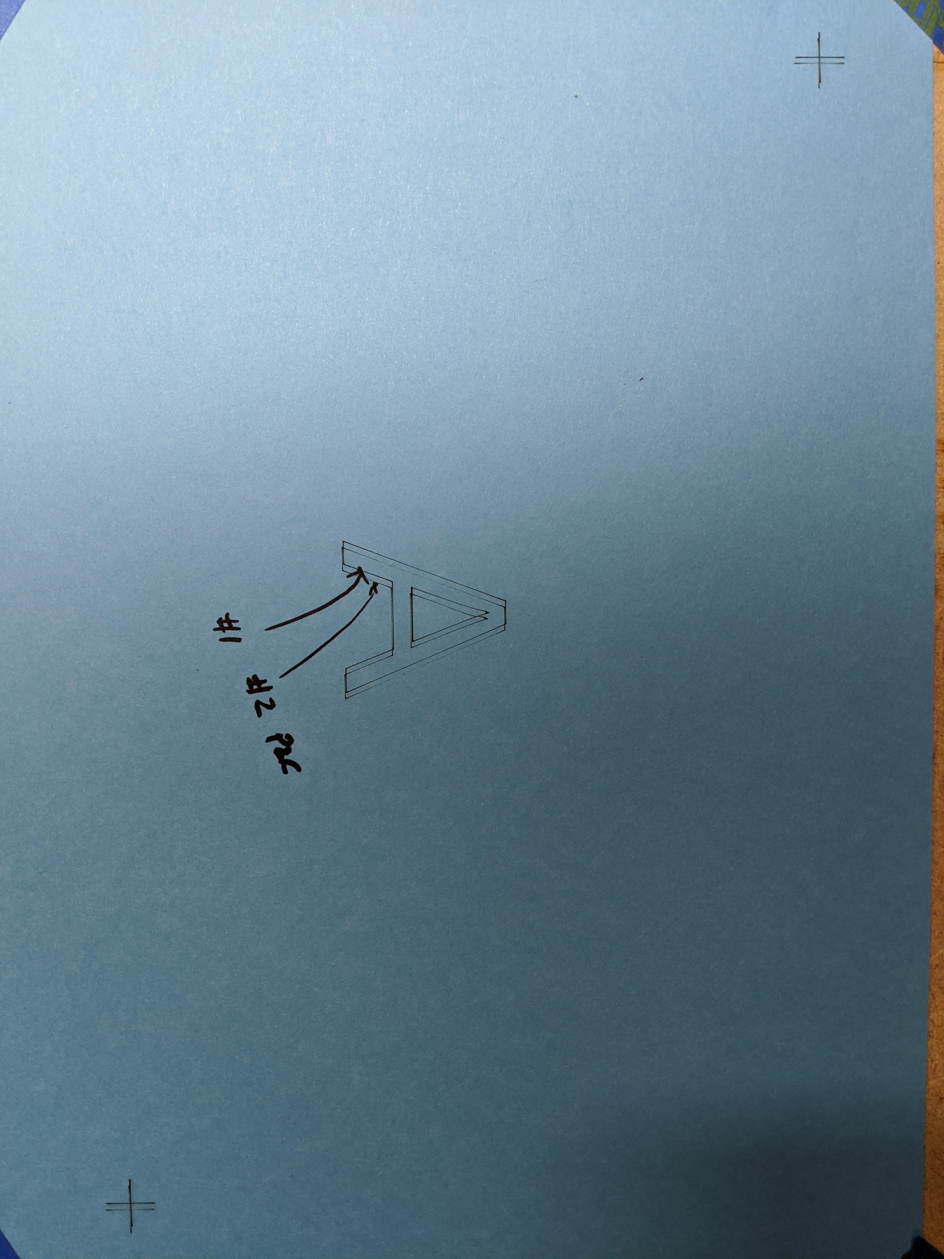
I make a drawing with 2 crosses at corners and a single letter A.
I run the job in normal “current position”.
All fine.
Then I use the two corner crosses to align a print and cut of the same job.
Should land right on top right right?? Nope.
Offset by quite a large amount.
Double checked the red-spot and pulse hole are coincident and indeed they are…really very very closely aligned. Yet job is all around 1+mm offset to right. For ref that A is set to 50mm (so comes out about 35mm tall). Note that even the crosses are offset in X. But not in Y!
How exactly are you “zooming in”? Are you using the camera for this somehow? If so, that will be the problem. Print & Cut is meant to be used without it - you just use the red dot pointer of your laser to align the head to the registration marks.
I think the most telling thing is that if I run a print and cut job on top of the same graphics done using “current position”, I get the offset shown in the pic. That baffles me. Using the crosses as the datum it misaligns relative to the first pass.
To answer your question I simply mean in the graphics area…zoom in and click the middle of the cross to move head to that position…it doesn’t end up there…instead it’s at an offset
Just for completeness I just reran the job first in absolute then an aligned print and cut on top as second pass. Exactly the same outcome…p&c run comes out about 1.3mm to right
Do you have a red-dot pointer offset applied anywhere? There really aren’t many things that can affect this. A pointer offset is about the only thing I can think of.
It is, bang on to 0.1mm or so. I also tried a reduced size test of around 50mm sq and it does the same. So big or small I get around 1.3mm offset…quite big!
I’ll do some more digging later. I noticed in the controller there’s an option not to move after finishing so I’ll do that, read the coord at the panel and in LB and then do a manual move to that same place and see if it budges…should not move at all I reckon.
The non readable log… where can I find that? I’m not averse to a bit of hex editor squinting
Finally resolved!
After lots of experiments I noticed that my results weren’t even consistent. Doesn’t sound like s/w!
So, back to doing everything super carefully and it comes out spot on. Accumulation of several small-ish errors looks pretty nasty in total…because the p&c is scaling, offsetting and rotating too.
Anyway…after actually using a pulse to confirm the alignment before locking to that feature showed a couple of 0.5mm errors that combined amp-up to >1mm overall error sometimes. Just need to figure out how to reduce those errors and I’m good
Phew - I’m happy to hear this is what it was, because I couldn’t think of a single thing other than the pointer offset or stepper slip that might be the cause. All the tests I’ve done with it have come out perfectly (or as perfect as my inputs allowed), so this is a relief - thanks for the follow up.