Accuracy & repeatability

Hi,

I have a 6 month old OM Tech 6040 55 watt CO2 laser.

Trying to cut a pattern of precision slots in .125" acrylic. 6 rows x 2 columns. Slots need to be .375" (critical) x 2.5" (not critical). Cutting 2.5 on the X axis.

Settings are .45 inches/sec and 35 power.

Each row varies from about .375 to .378

I previously had a ULS 25 watt that held this pretty tight.

Any suggestions on settings, or adjustments? Or am I expecting too much.

Thanks,
Jeff

I can imagine that this variation gives you problems with topics that need to be press-passed.
Have you tried to make the largest possible circle on some cardboard or other suitable material, to see if variations appear more clearly? To rule out mechanical problems, it is also good to cut a large square and check the length of all 4 sides.
A completely different option (regarding acrylic) is to slow down your speed, to rule out that the edges you ā€œmeltā€ when cutting, do not cool evenly and thus vary slightly when it goes from liquid to solid again. I hope you understand my strange wording.

Another option is to use MM, not inch.

Rounding errors in converting inch - mm can cause small differences.

Your machine works in mm, internally.

I cut acrylic using LB all the time and get an interference fit.

bernd.dk,

Good suggestions, but Iā€™ve tried all of that. Did a few test squares when I first got the machine and recently to confirm.

I have also tried various speeds with no change.

Bo,
Good thought but unfortunately no luck with that either. Changed LB to metric and created new shapes so all outside errors were removed. Still no success.

itā€™s a shame to hear, I hope you find a solution anyway.

Make a series of objects and holes in LB with different settings until you get an interference fit. Play with power and maybe the kerf offset until you find a setting that works - remember that kerf offset can be outside or inside the cut, depending on whether you set a positive or negative integer.

Screen Shot 2021-04-06 at 5.39.55 PM

Thatā€™s what I do when processing a new material and is the right way to do it.

Unfortunately itā€™s not for joining parts. Itā€™s a sorting process that requires a part to drop through or pass over the slot. I have a support request in to OM Tech. Weā€™ll see how that goes.

Greatly slowing acceleration seems to have helped a bit. While each slot does vary, the variance seems consistent from part to part. Iā€™m experimenting more with that now. Might be able to just find the right dimension for each slot. Sloppy, but if it worksā€¦

Can you space the slots out more or less? Plus or minus a mm or two. See if that helps.

Might be something to do with the steppers and microstepping.

Would a better driver help this issue?

That doesnā€™t matter - the process for working out your material tolerances is the same. Whether itā€™s a friction-fit or a coin-drop, the design and build process is the same - make the hole the right size.

Is LB really that sensitive to the measurement system used. Iā€™d be really surprised if that was true.

It seems more likely to me that the problem is looseness in the motion system somewhere, a slack belt, loose grub screw or something similar. One way to test that might be to cut a sample part a dozen times or so and see if there is any dimensional variation amongst the parts. If there is no variation then it might be a dimensional unit issue.

Or it could be an issue with the instruments - cheap import calipers might vary by that much, sample to sample. Or maybe it is a variation in the cut surface - 0.002" is about half the thickness of a human hair and acrylic can have a sort of corrugated cut surface.

It has nothing to do with ā€˜sensitiveā€™.

All laser controllers operate internally using base 2 - so does your computer. To use inches requires multiple conversions from inch to mm and back, with rounding errors in every direction.

Say, internally, an app uses a byte to represent the low-order part of a decimal (because neither computers nor controllers ā€˜understandā€™ the concept of a decimal or a fraction or a degree - whole numbers only in binary - https://www.electronics-tutorials.ws/binary/binary-fractions.html - which, again, requires calculations both ways, discarding least-significant bits along the way.

Do that enough times and it can make a measurable difference to the workpiece.

This doesnā€™t happen in metric units.

So, a simple question - do I use the system of units that loses accuracy or the one that doesnā€™t?

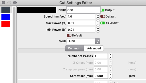
@LightBurn can give us a definitive indication of how many significant digits, so we can work out how much gets discarded.

There has been some real-world instances where using one or the other has resulted in a significant, observable phenomenon.

Back in the day, when I first started work, my boss told me about his early work. He designed and built analog tracking systems for military rockets, guns and cannon.

It was all feedback loops and mercury relays and vacuum tubes. They didnā€™t care about metric or inch, their stuff was all in miles and degrees, so calculated on base 60.

He spanned the period from the 1930s to the 1980s, encompassing ā€˜the digital revolutionā€™ and was the smartest Texan I have ever known.

My job was, initially, what they called FEP programming and design - the Front End Processor was the part of a computer that took signals in - digital and analog - and converted them to digital for the computer to work on. A DAC, more or less.

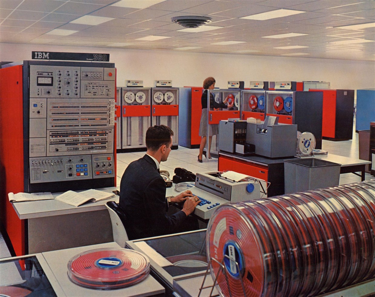
This is the 8-bit, 131,072 byte computer in question. There were no girls. We didnā€™t wear suits. We had long hair, wore sandals, board shorts and Mao/Che t-shirts.

I just couldnā€™t get my analog signals right, no matter what I did.

He, in a very Strangelovian manner (Dr. Strangelove or: How I Learned to Stop Worrying and Love the Bomb) taught me how to stop worrying and learned to love analog.

I was chasing perfect, and I was the enemy of good.

My processor was ā€˜huntingā€™, up and down the analog signal and my results were spurious. He, coming from a military targeting background had the military mindset that it really didnā€™t matter what you did, as long as you hit the target or knew what was going to be hit.

But, he and they were looking at accuracy in the region of tens of yards. A battleship makes a big target, so does a factory. A fighter jet, less so, and it was the high-speed planes that spurred on the revolution to digital accuracy.

So while 0.005" might be half a human hair, braid enough of them together and you can jam up the works of a 1052 Data Communications System, shutting down the works.

Pass a file around enough between America and the rest of the world and it can introduce errors big enough to matter.

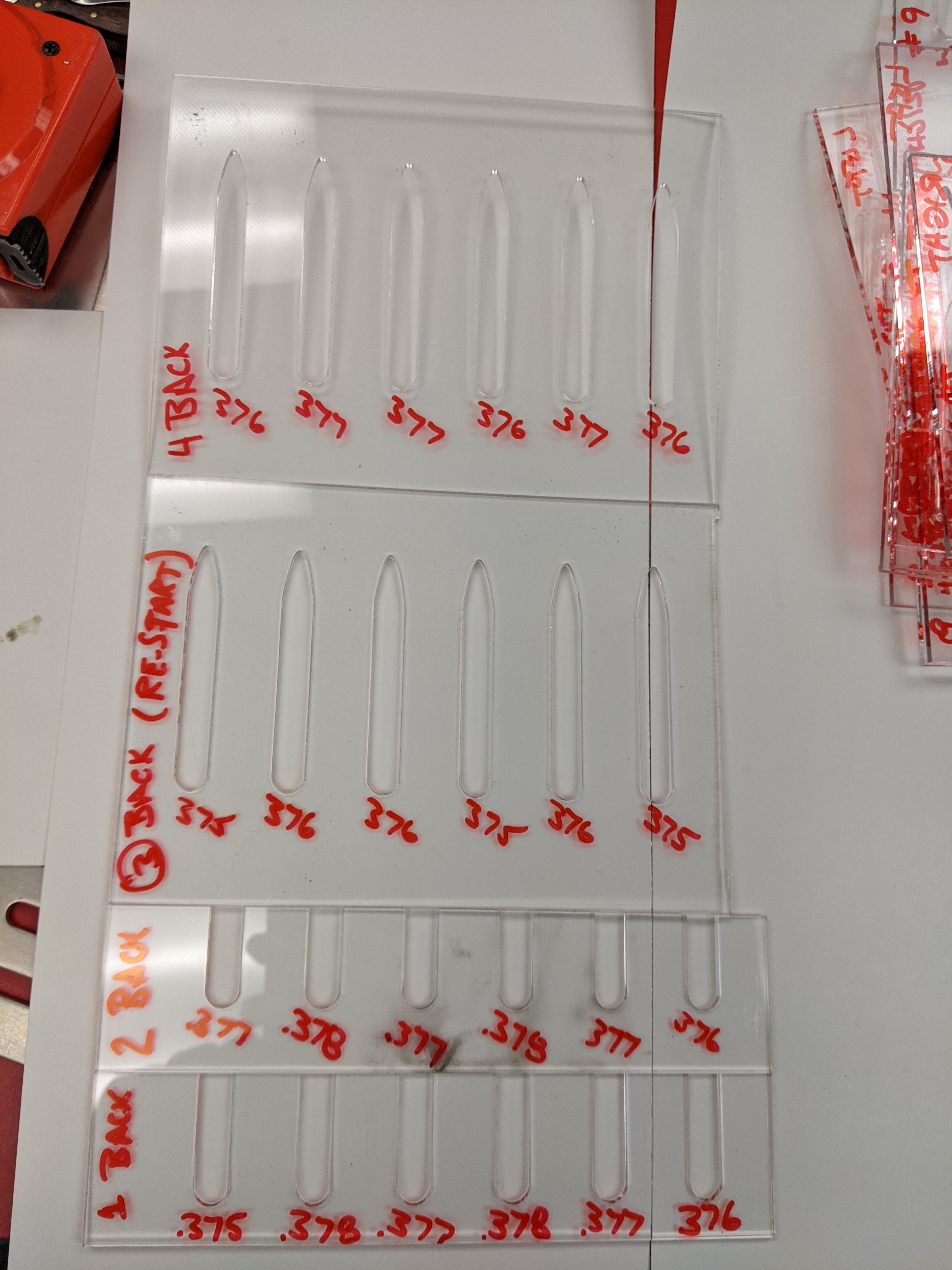
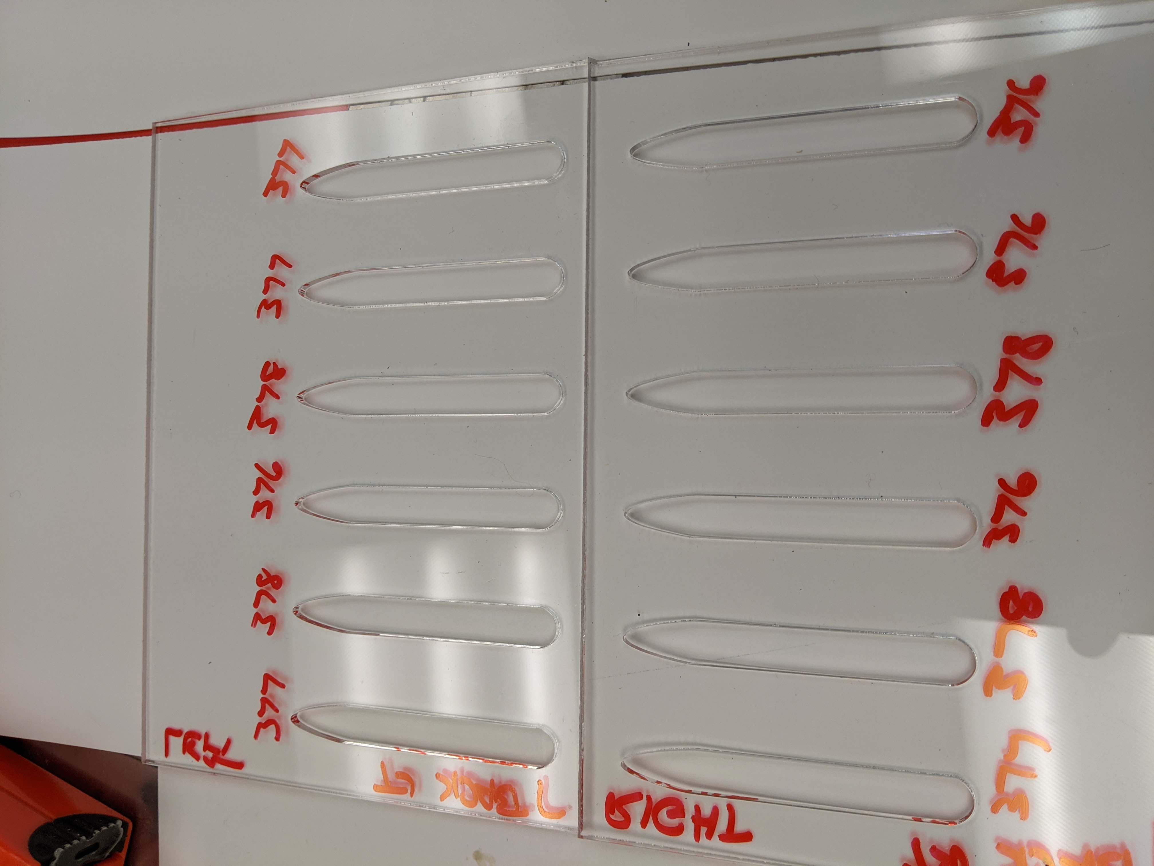
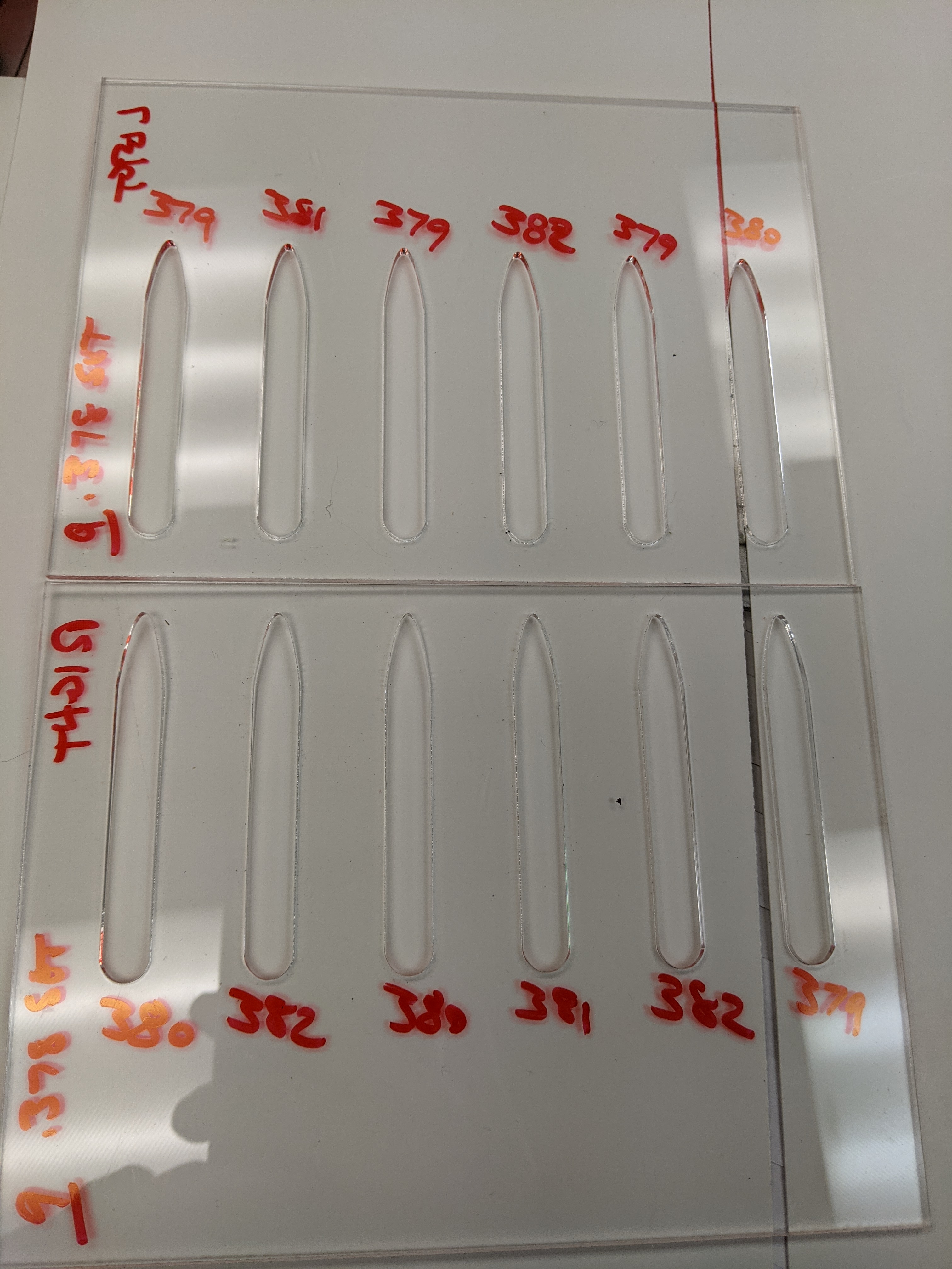
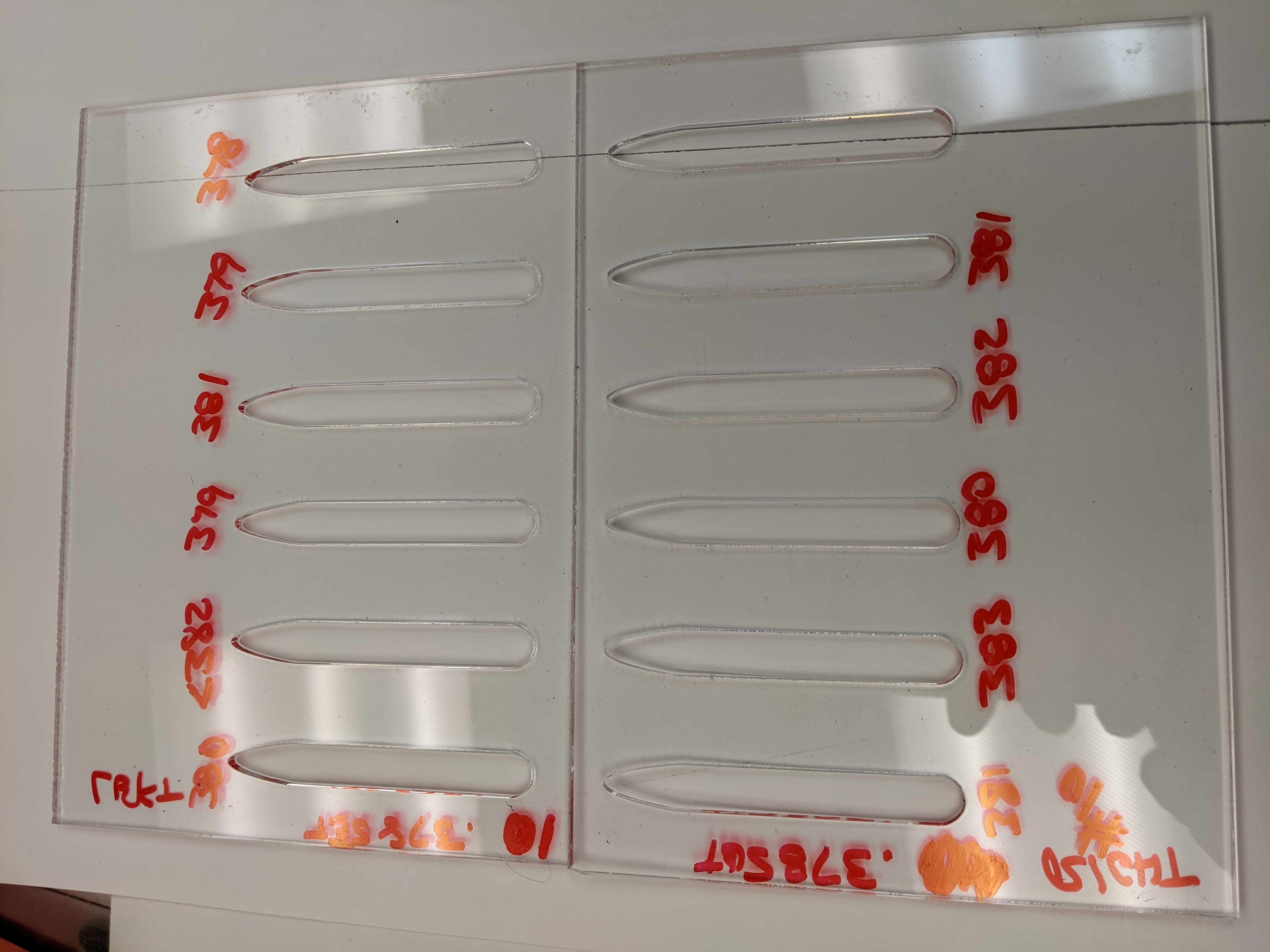
This happened to me yesterday - my friend and I swap designs - she in Philadelphia uses inch, I use metric. Her file was sized for ā€˜3 mmā€™, but it really was 1/8" and I cut it on 3mm and it was sloppy as heck. I fixed it, updated the file, cut a sample, photographed it and send it back to her and she cut it and it wouldnā€™t fit - which is, of course, completely different to rounding errors, but it is probably more relevant. A 0.175mm difference in dimension, every 3mm, results in a completely different object.

Using the Roman uncia, using fractions, in the 21st century, on digital machinery is counter-productive.

1 Like

LightBurn internally stores everything in mm and simply displays inches when requested. The conversion is 25.4mm to an inch, so thereā€™s not too much loss, and everything sent to a Ruida is rounded to 10s of microns anyway.

LightBurnā€™s default precision is 0.05mm, which is about 2/1000ths of an inch. Drop that to 0.02mm (in the main settings page, at the bottom of the ā€˜File Settingsā€™ tab, called ā€˜Curve Toleranceā€™).

That setting controls the precision used when arcs are converted to line segments, and is the maximum allowed error. Average error will be half that.

Having said all that, acrylic liquifies with heat, and will flow / warp / etc (at least locally), so you might be expecting too much from your laser.

2 Likes

Thanks.

What about when a file - dxf for example - is imported, having been created in inch? Is it internally in metric, too?

Itā€™s converted on load to mm, yes.

1 Like

So after A LOT of testing, I had it down to .002 deviation, or so I thought. Pretty good, but still strange that it changes from 1 print to the next.

My sole issue is consistency. Slot were measured with Class ZZ gauge pins. The pins were double checked with a high quality digital caliper.

Test #1 to #7 were output with the document set at .375". Iā€™m aware of kerf issues and adjustments. Variations were down to .002 with an occasional .003" Understandably it was always cut larger than .375.

Looking good so I adjusted the file to .378" to hopefully arrive at my maximum allowable .380". Test #8 was within .002. Feeling good so I run a few more tests. #9 was within .003. Test #10 (2 pieces cut together the way the final part needs to be) and weā€™re back to .005" variations. See bottom row, column 2 at .383" and top row, column 6 at .378" #9 was cut on 2 pieces same as #10.

A few adjustments I made were to slightly reduce acceleration in both X and Y. I also changed each column to a separate layer/color so it would cut 1 column and then move over and print the other.

On the issue of acrylic properties, I also did the tests multiple times with heavy poster board.

As Oz suggested, I am wondering if Iā€™m expecting too much from the laser, but I would think, possibly incorrectly, if it could achieve engraving resolution of 2540 DPI this should be attainable. If Iā€™m doing the math correctly, thatā€™s .00025?

I have a support call in to the distributor and they have just responded asking for samples. I post the response when I get it.

Thanks again to all that have made suggestions to try to help out.

Jeff

Your math is off - 2540 lpi is 0.00039". If you look closely at the cut edge of the acrylic you will probably see that the edge is slightly jagged and those little zigs and zags will result in slight variations in the measured dimensions.

If you expect accuracies in the range of 0.0004" then you should consider a CNC mill and expect to pay $50k (possibly much more). You probably need no where near that accuracy or precision though.

What sort of error would you expect in that conversion? Possibly too little to measure with common instruments?

Thanks for the corrected conversion. I knew I was probably off there.

Iā€™m not expecting .0004 by any stretch of the imagination. I was hoping for .001 or even .002 would be great. I was getting that on my 20 year old universal. 25 watt.

My cut quality is really good with no discernible zigs or zags. If I run a fingernail over any cut surface, there is no sign of rough cut.

I realize these are really inexpensive machines and what Iā€™m really looking for is consistency.Itā€™s really frustrating to reprint a job and get different results each time.

OM Tech asked for a video that I just made this afternoon. I assume there are others with this brand, so Iā€™ll keep everyone informed on what to expect from them.

I would expect no discernable error in that conversion at all - probably looking at 7 or 8 decimal places, in mm.

1 Like

Well less than a micron then so the OP must have another problem.
.