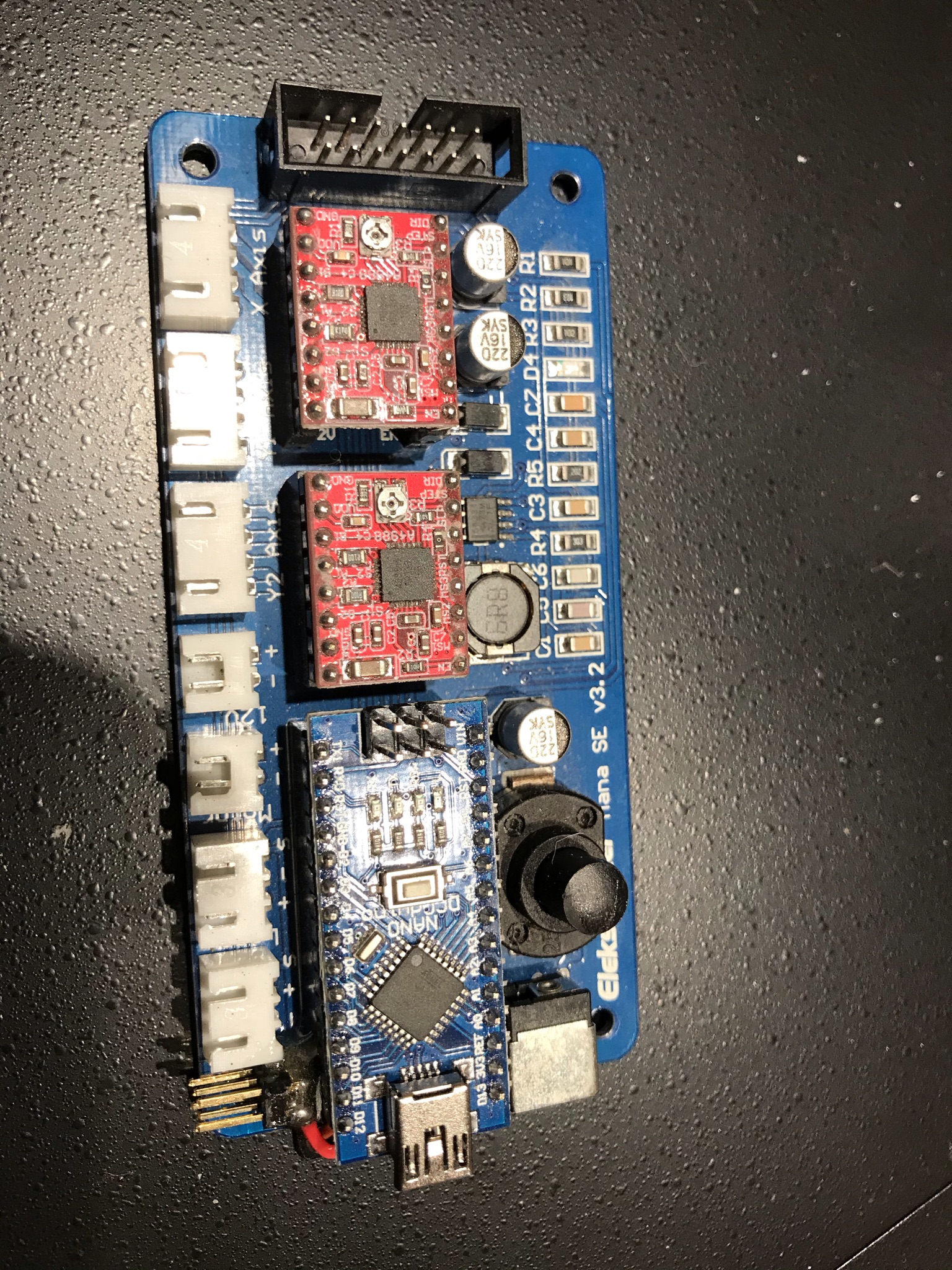
My laser engraving started out with an Acro Laser using the Eleksmaker Mana SE V3.2 board and a 3.5W diode laser. I have since migrated to a CNC shield V3.0 to add a Z axis to the Acro but the original Eleksmaker Mana worked well.
One thing I did not have was limit switches. Limit switches are REALLY useful, not just to keep things from going out of bounds, but to set a fixed accurate known reference point.
The Eleeksmaker came with GRBL .8 as I recall and that didn’t support limit switches. I decided to upgrade the board to GRBL 1.1e by using another program called T2Laser that I had tried. I didn’t stick with T2Laser but it did allow one to flash firmware easily without learning things like Arduino IDE etc…
GRBL 1.1e allowed for limit switches BUT the Eleksmana SE has nowhere to plug them in… THATS what this post is about… adding that feature.
GRBL looks for limit switches in a really cool fashion. The limit switches are all in parallel… ANY limit switch that closes will tell the board the limit has been hit and it only requires ONE pin on the nano board to do it! D9…
How does that work… first understand how the limit stuff works… assume the laser is in the middle when a homing cycle starts. First it moves X to home at a fast speed waiting for a limit switch and when it sees a limit it then backs away slowly 1mm which is far enough to open the switch, then it heads towards home on the X axis again but SLOWLY to get an accurate position for the limit switch closure. Then it backs away 1mm, done for X. Then it does the same thing for Y axis. The switches are in parallel so first the X axis switch triggers pin 9 then later the Y axis switch triggers pin 9… brilliantly simple.
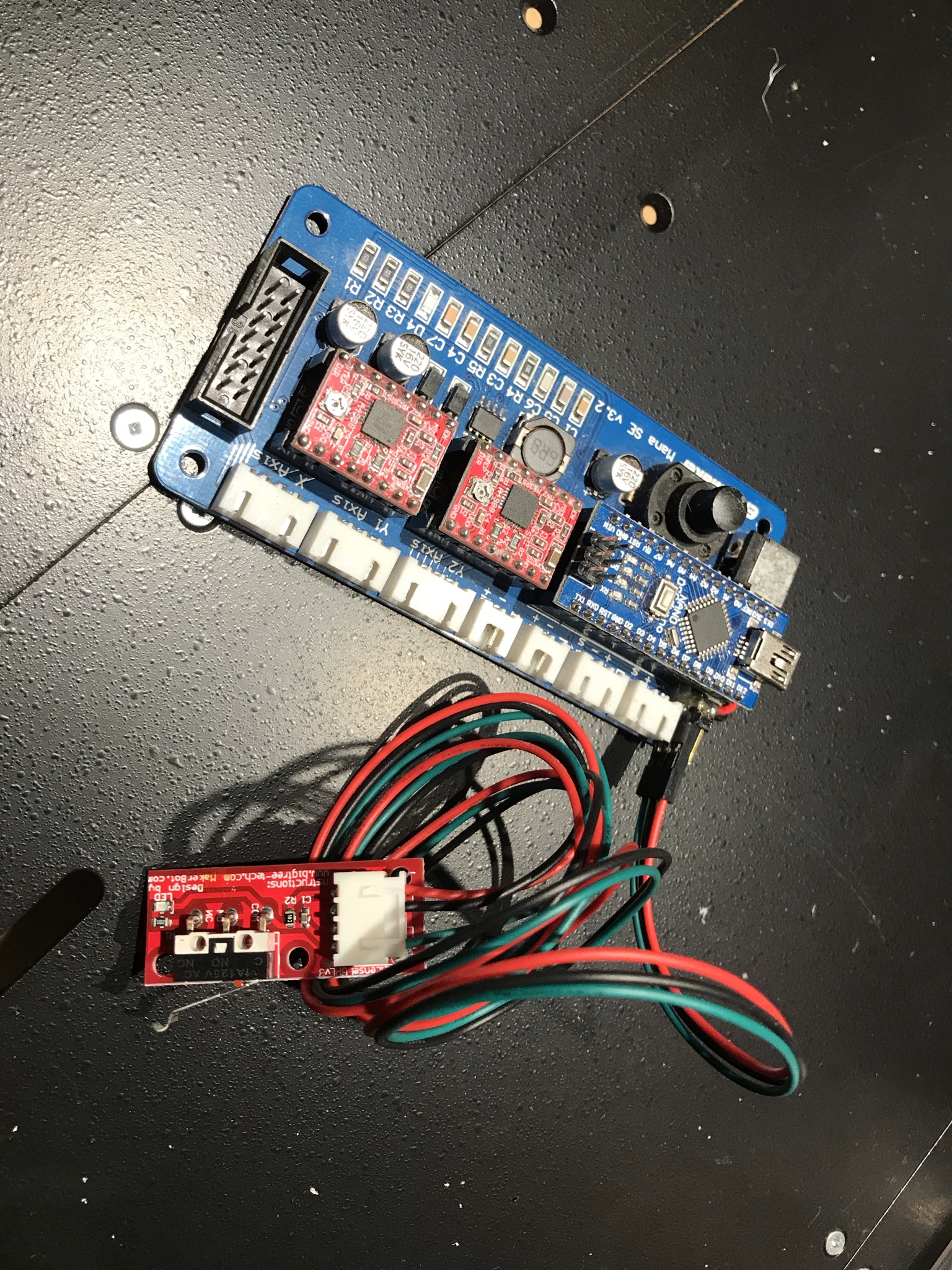
So how are we plugging two limit swithes into D9… Well typical cheap limit switches are a 3 pin dupont connector with Red Black and Green wires. Red connects to +5V, black connects to Ground and green is the signal that we need to hook to pin D9. I took a dual row 3 pin header strip and soldered 3 wires to the (my wires just happened to be Red Black and Orange so I used Orange as the signal which connects to Green on the limit switches.) And I connected the two rows in parallel.
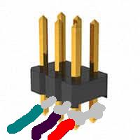
Crude pic but you get the idea.
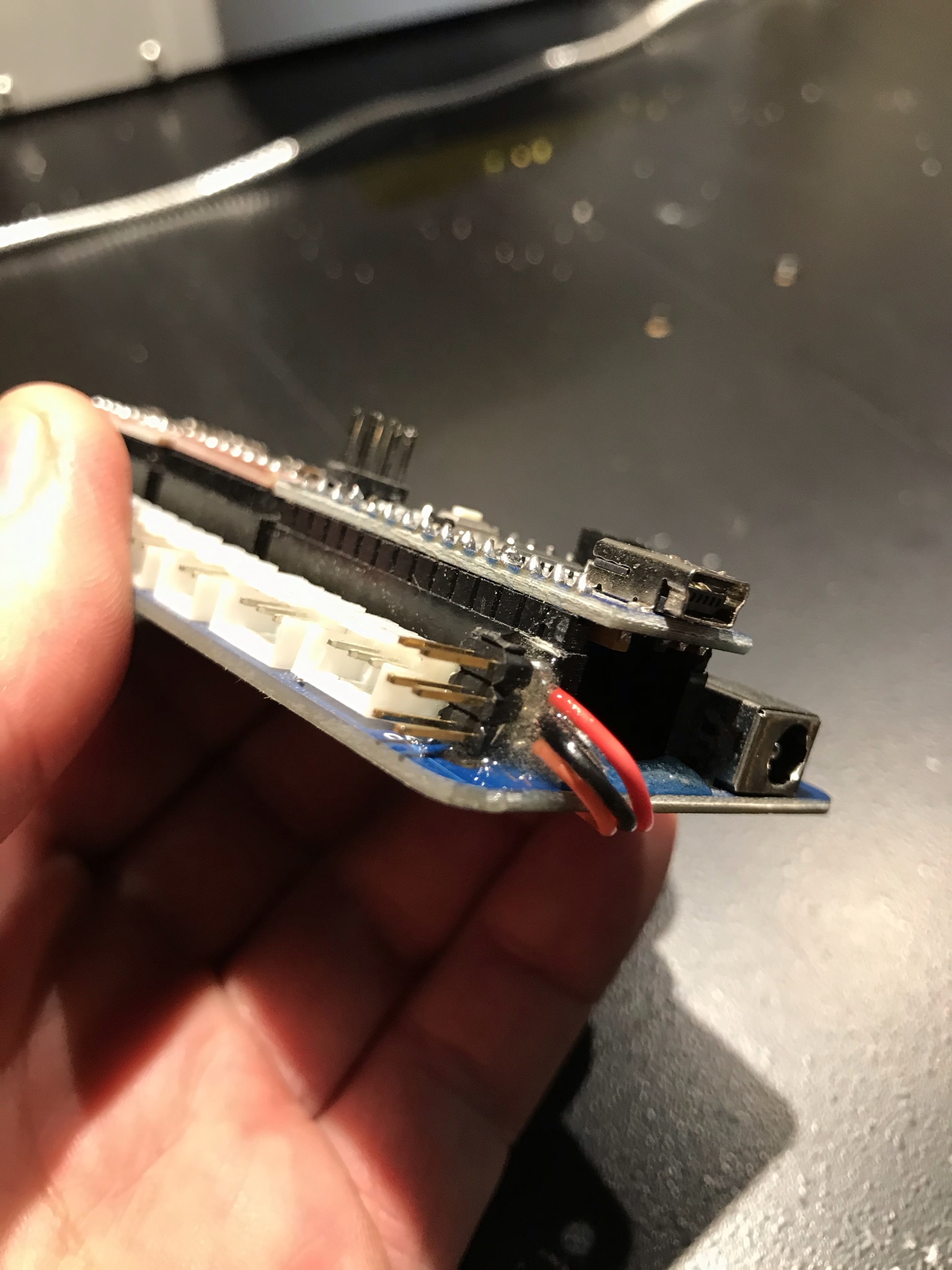
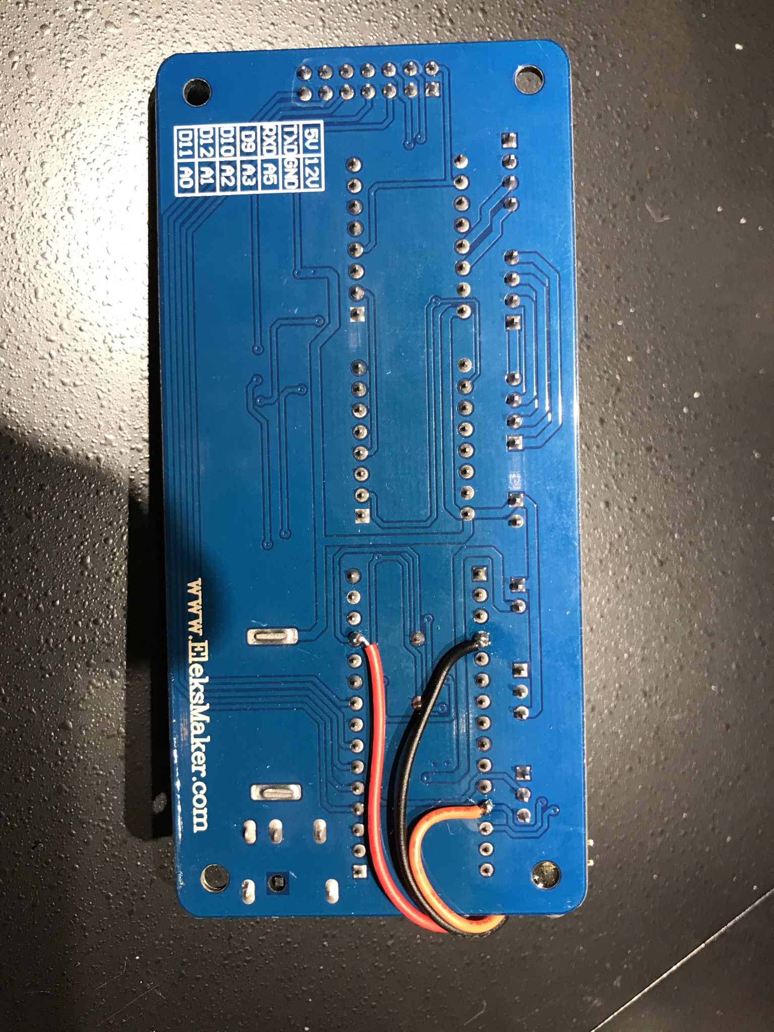
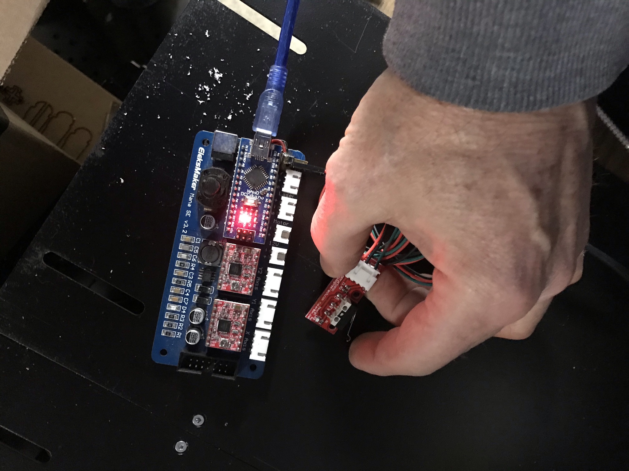
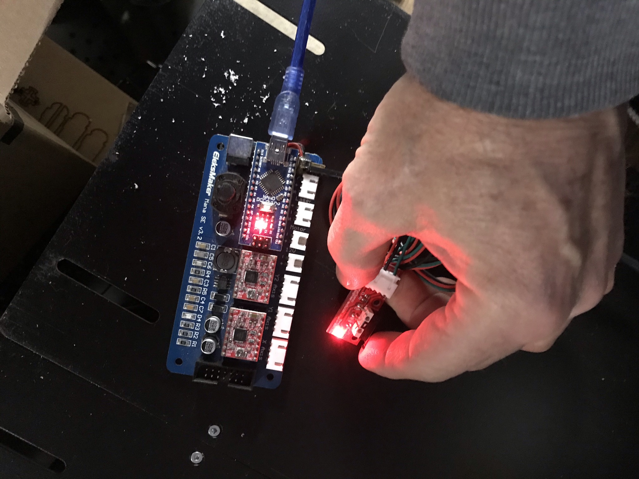
Then I just epoxied that header to the board at one end and ran the wires underneath and soldered them where they needed to go… As it turns out, ALL wires connect to the 4th pin from the end… The green (orange in my photos) connects to the 4th pin from the USB connector closest to where I glued the header (D9). The black ground wire connects to the 4th pin from the other end on the same side as the green wire (Gnd) and the red wire connects opposite the black on the 4th from the end furthest from the USB connector (5V). See photos for how I wired these. Careful not to bridge solder to any of the nearby pins or you could damage your board.
Hopefully this helps some other newbie doing similar upgrades.