Hello,
I have a chinese laser, which I bought a year ago or so, without Z-axis. I built a manually adjustable bed with 3d printed pieces and metal parts.
Now I would go further to motorize my bed.
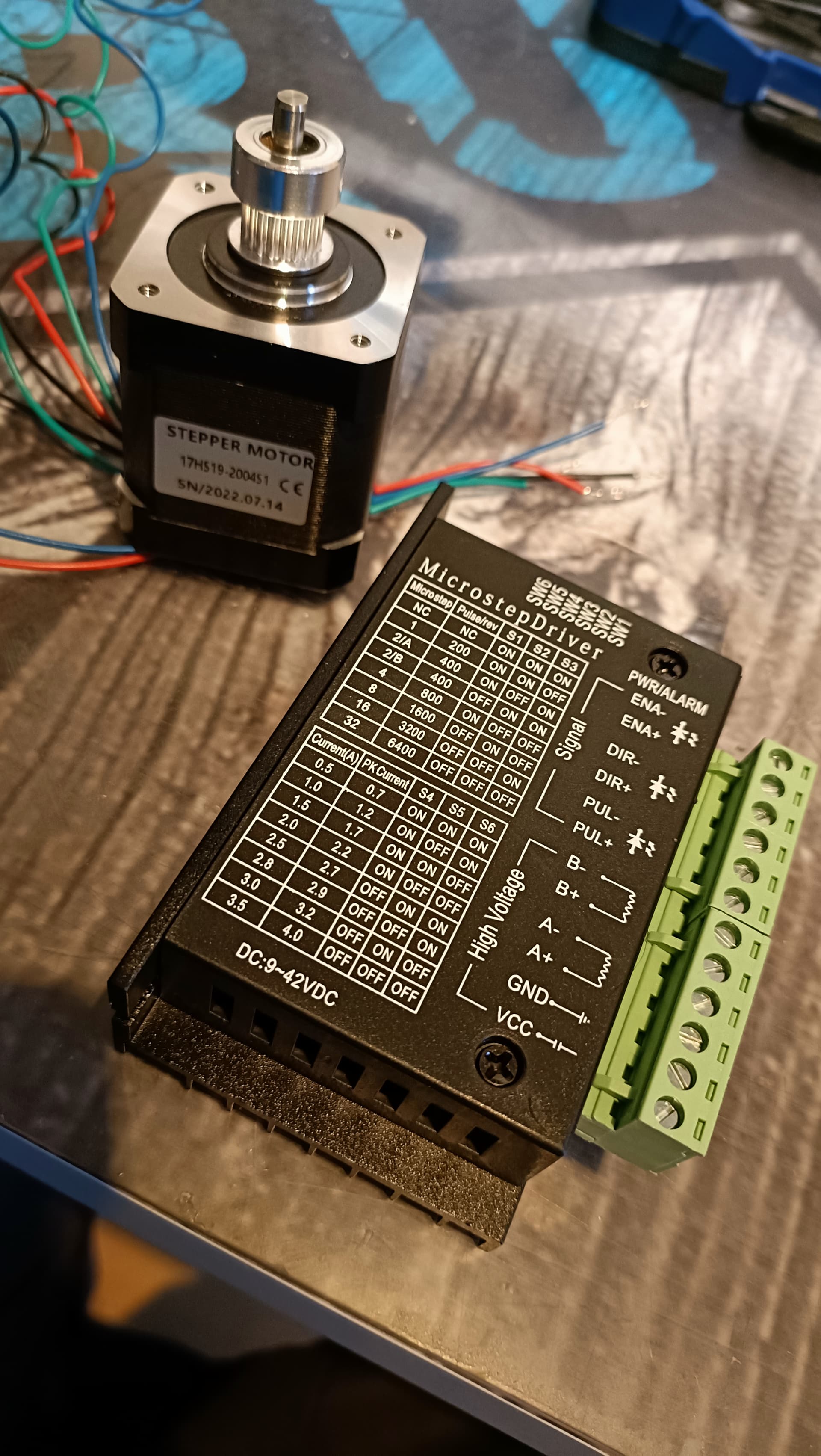
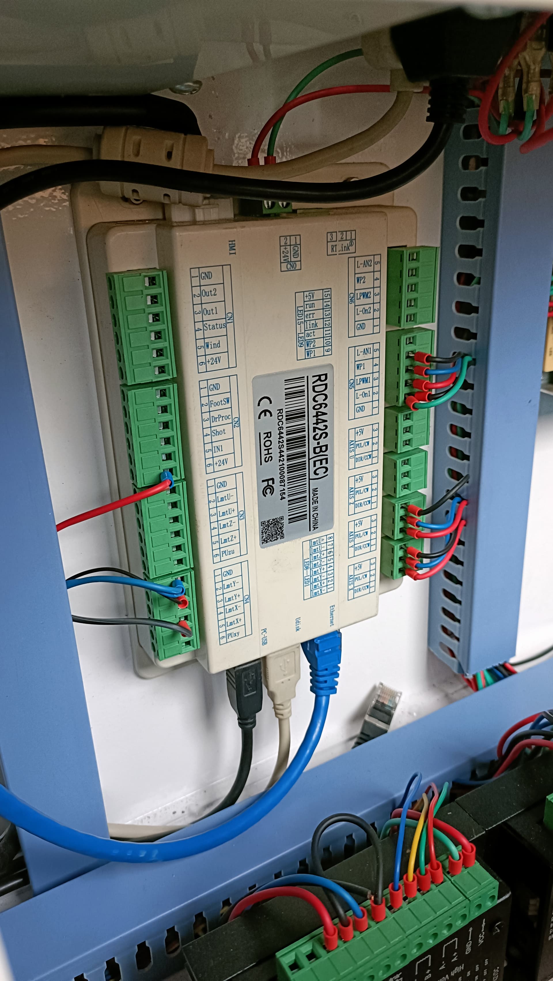
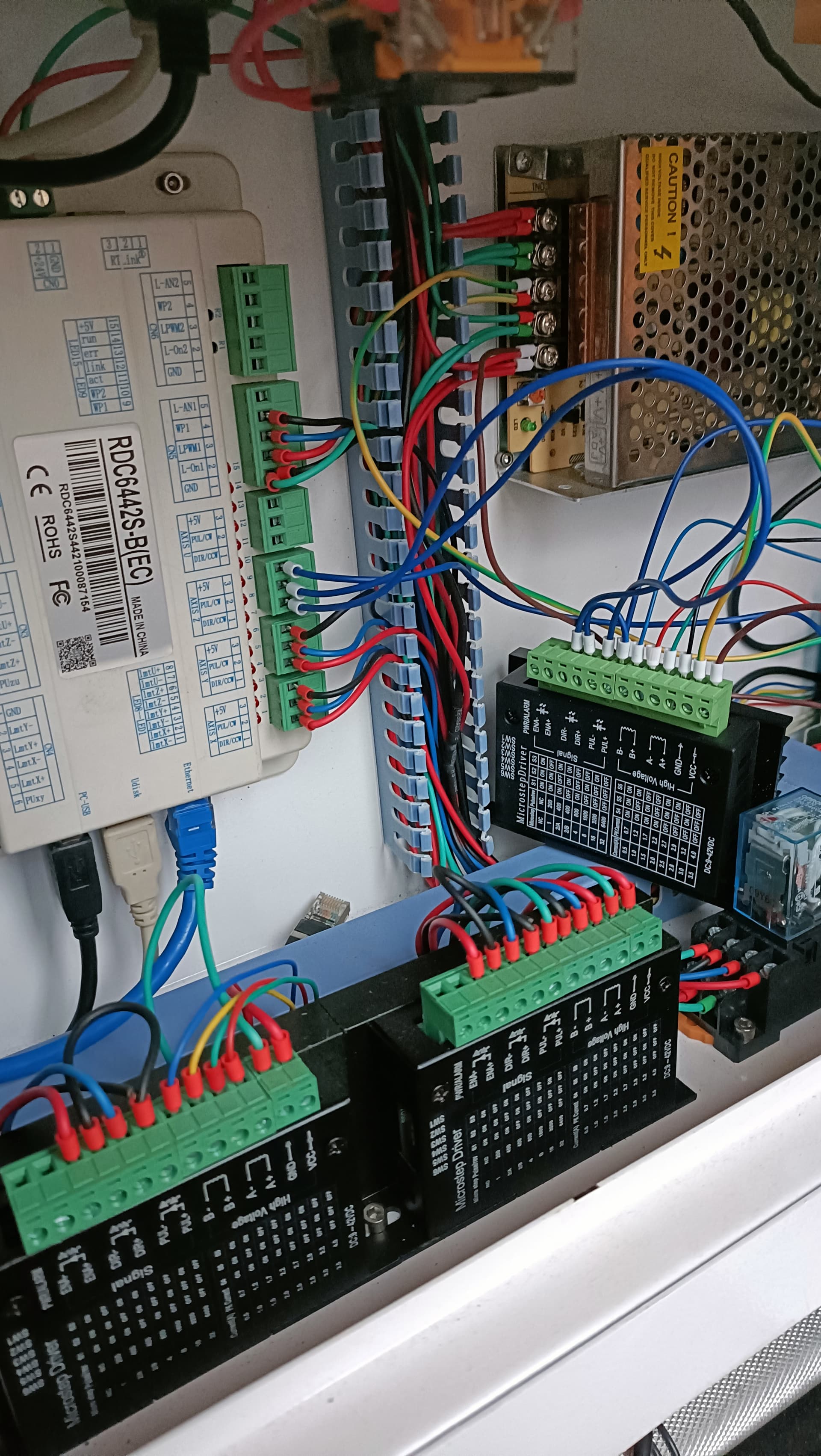
I have a RuiDa controller, and already have a Nema-17 stepper motor and a TB6600 Stepper Motor Driver.
From here, I’m stuck with the wiring part. I don’t know how to wire the stepper motor driver to the power supply (if I have to), and the nema 17 to the stepper motor driver.
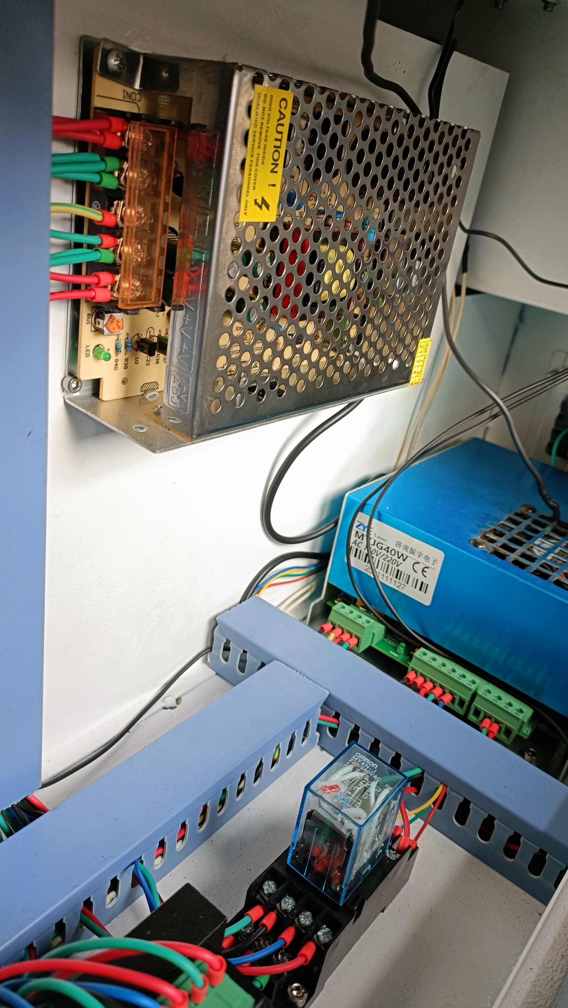
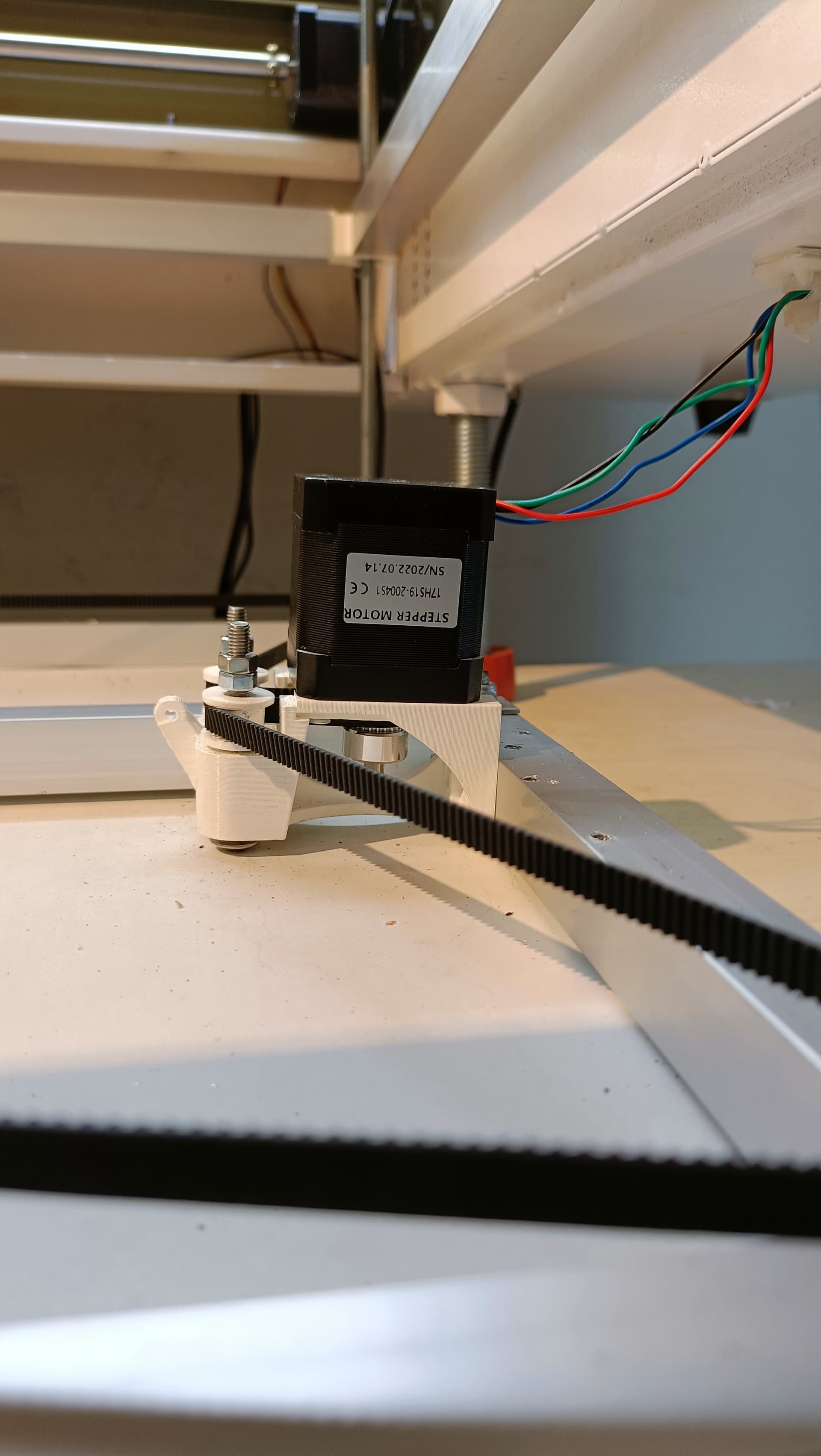
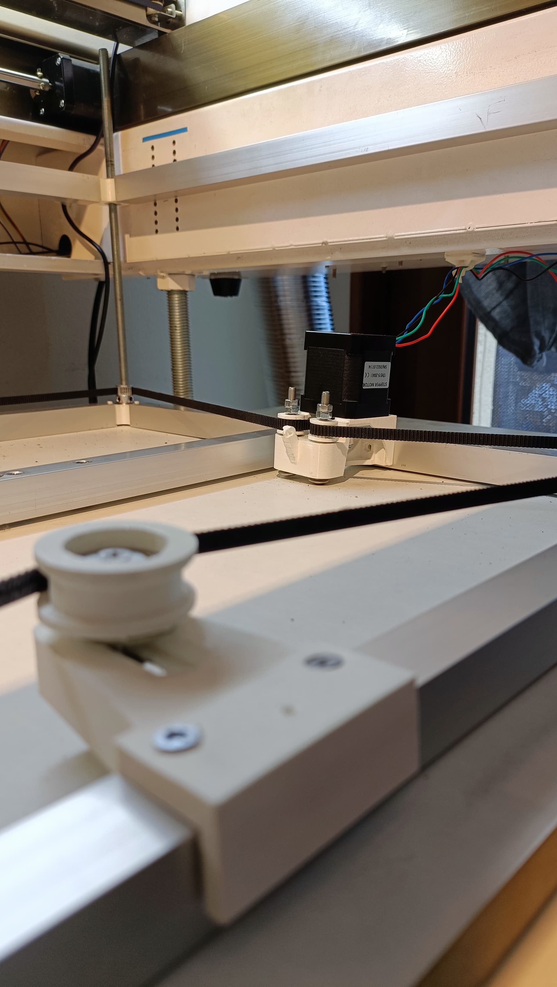
Can someone help me with this please ? I add some pictures of my installation and hardware.
Thanks a lot Berainlb, I will keep those informations.
Here is the link where I bought the stepper motor driver, to verify: Aliexpress - Stepper Motor Driver
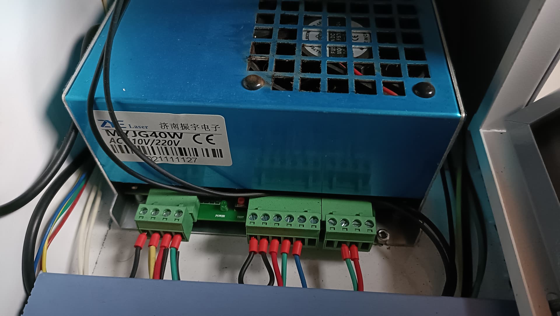
You said 24V supply, so it’s on the grey one on the left? Not the blue one, right? And as I see there is not a lot of available space for new wires on it. I think it’s actually mainly used for the rotary motor (with a switch (Y-Axis/Rotary) on my machine). Should I get a different/extra power supply? Sorry, I’m very not aware of all those electrical things.
Yes. Definitely not the blue one. Blue one is LPS - Laser Power Supply used to excite laser tube.
This should be powering all the components of the machine other than the laser tube. So your controller, all other steppers, etc.
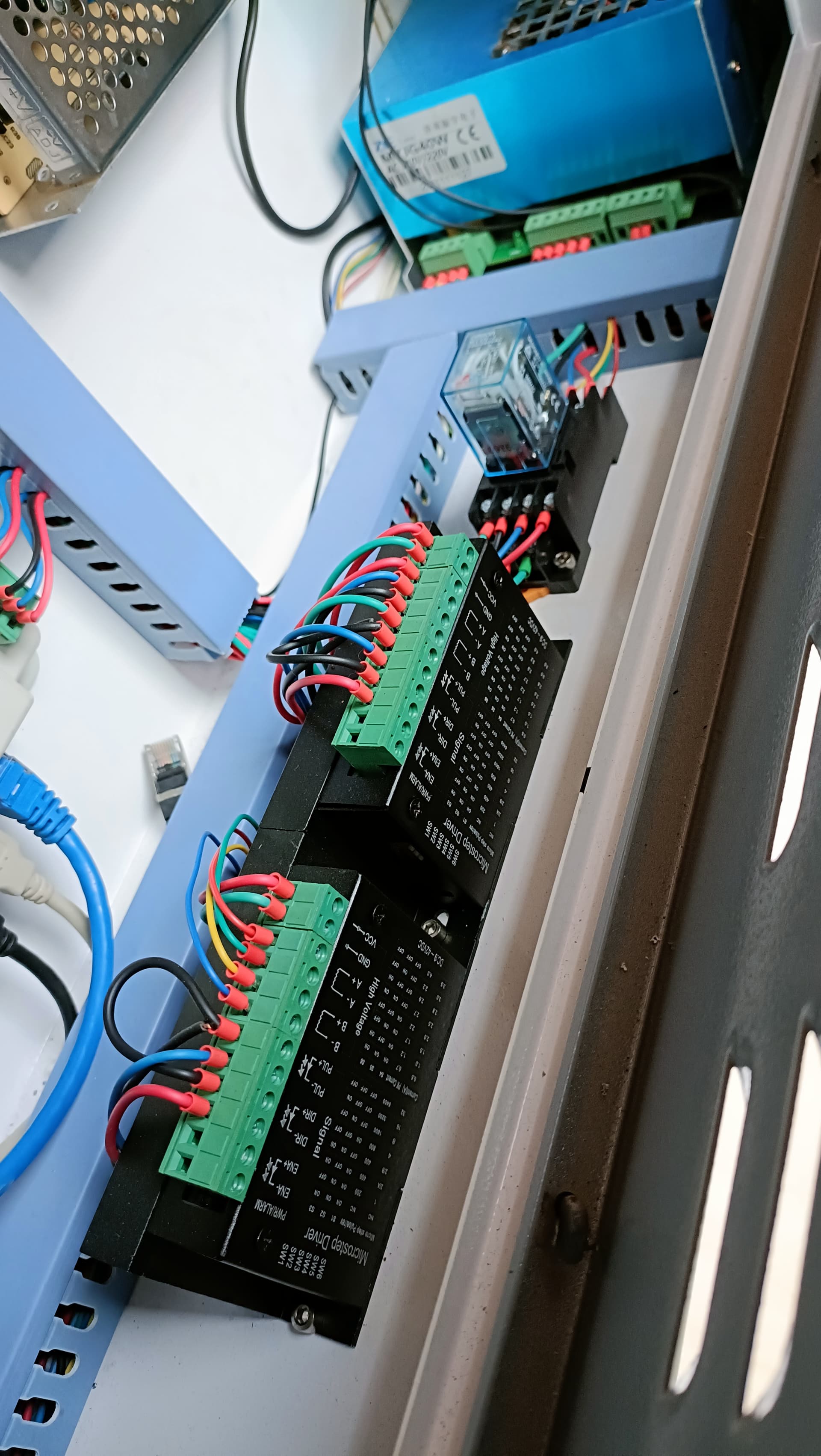
You could get another supply. That would work but likely not necessary and create other challenges. Check how the other steppers are connected to power. You should be able to double up those wires.
You could confirm the power supply ratings and add-up the current requirements for all your equipment but generally this will be fine and it’s likely the same power supply is being used for machines that have motorized Z and machines that do not. You could replace the supply if it proves to be underpowered.
I don’t know if the Z stepper is kept engaged the whole time the machine is on. If it’s not then this isn’t likely to be a concern since Z is infrequently used and when used not concurrently with other steppers. Even if it is kept engaged it’s mostly just holding.
You could reduce current to 1A to start which might not be a bad idea anyway. Then increase it if you’re not getting enough torque. For Z this shouldn’t be a big issue.
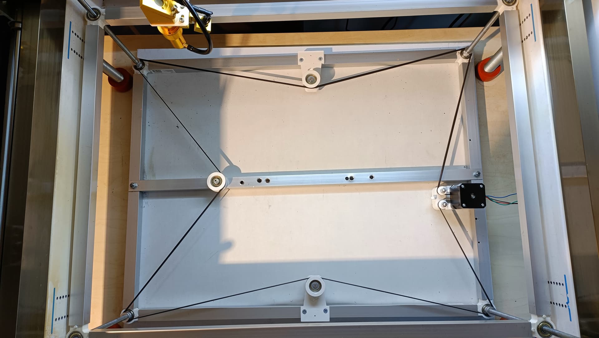
Now I have a “last problem”, as you can see on this video, the belt is not moving, it’s like it’s missing teeth on the GT2. Do you know what can I do to fix this? The belt is new and tightened, and all of my pulleys have 20 teeth.
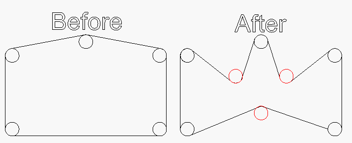
As for the issue… I can’t see your whole belt path in the video but it looks like you have very little tooth engagement between each pinion and the belt. Between that and belt tension issues the belt is likely slipping on the stepper motor pinion.
You could try to address this a few different ways:
Get larger gears. This would allow more teeth to be engaged. Might be useful at the corners.
Reroute the belt so that angle to each gear is increased.
For tension, you probably want a tensioning pulley that is adjustable where you can vary the amount of tension being applied.
Thank you very much for your explanation. I’ll think about that, even if it’s a bit strange, as it worked before just with the 4 corners, when I changed my Z-axis manually.