I have a Longer B1 30 watt laser that I want to add a Z axis to. I can fake a third axis by a method I figured out but would prefer to use an onboard on if it is actually there. I can not get any pinout information on the control board and it is sparsely marked. Right next to the two marked X and Y axis connectors are two others each with 4 pins. There are vague references to Z axis elsewhere on the board. There are two heat sink topped chips but I can not tell what the chips are or if they each support two axis or just one each. I do not want to just connect a motor for testing in case whatever is connected to these sockets might be damaged by the load. I couild make up a tester with LEDs to see what signals are on the socket while joggin the Z axis from LightBurn if that is possible but will still not know how much current capability is on the socket. It would be great to find real documentation. BTW the control board uses an ESP32 because there is WIFI support which I never used. Of course I also can not find pinout information to see if there are step and direction pins for the Z axis. Schematic please?
Can you provide some pictures of the board?
You probably have an X and 2 Y’s and then Z connectors.
the four sockets on the bottom from the right are all the same and not marked so the fact that it is dark is not significant since there is nothing to see. the two sockets to the right are marked Y and X axis. this machine has just one Y axis motor i wrote to manufacturer but have not heard back yet. do you think if i put a tiny stepper on the other sockets i could test without blowing it up. since i have no idea what the sockets might be i have no idea how much current they can source of if they are protected or who knows what
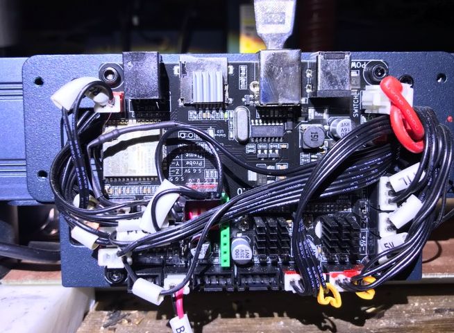
Sockets at bottom look like the steeper drivers. Sockets at right look like power/etc. Most things look to be marked.
Z axis motor would be same size or smaller than X or Y motors so driving it should be no problem.
that is what i thought but i did not want to connect a stepper with low resistance to something that might not be connected to a stepper driver. are there little chips that do two stepper axis at once? there are only two heat sinks on the chips near the bottom the heat sink at the top is probably on something else like a voltage regulator. do you think i should test with LEDs first and if they look like stepper phase voltages then be pretty sure that they are? the power supply to the board is 24 volts so the steppers could be given 24 volts. i should measure the one that i know is a motor output and compare it to the ones that are not populated
This is a derivative of MakerBase boards
I believe on Longer they have the Z not populated, you would need to move the cables away a bit to be sure
see the 2 small heatsinks, thats x and Y stepper drivers
But on the left of them it might be possible to add a stepper driver externa. you would need to take a bit clearre picture
it is marked LS esp32 v 1.0 and when i search for that with laser i get a link to a MakerBase board for $20 something dollars. I will check it out and maybe there is some Chinglish documentation. There is no room for another stepper driver so the only way this thing can do z is if the drivers each do two motors which i doubt. the other heat sink is on the SD card socket no other heat sinks. strange that the board has a marking -Z but not near anything other than maybe one of the esp 32 chip. I will have to use my other idea instead. making a fake Z axis by multiplexing using the air driver for switching between Y and Y !
unfortunately the maker base LS esp32 v 1.0 is a different board or it was replaced by v1.2 it looks like the only way to get z axis is with a different controller
not unusual
They keep the form factor and populate the chips depending on the “cost” of the series they are building.
No different from a BMW… you can buy it as little as 60k or 120k with extras. Silly example but you get what i mean.
What i would do - if i was you - is reach to Longer to know if you CAN use any of their newer machines Motherboard and retrofit it to your current one
And or if they can guide you on how to get Z axis.
They will know, and if they are willing to help with a bit of info might stop you going in a wild goose hunt.
thanks for the info but in this case (unless the two stepper chips actually handle two motors each) there is absolutely no space for another pair (or even one) of stepper drivers chips. There are no unpopulated traces on the board, none. I design and build boards and know that this is really true. I might try to remove one heat sink and see what the stepper chip is so I can find and trace the connections. However if it is epoxied on and not just stuck with tape the identification will probably be gone especially if they intentionally marked it out as many do. I wrote to Longer but have not heard back yet. For my own use it is not a problem to change boards but I was hoping to make a system for others who do not have the skills in electronics and machines that I have. And, my engraver is current production top of the line less than a year old.
I would definitly not remove the heatsinks
And i dont think they would remove markings, is not that important as the stepper drivers are common and face no “IP” risk what so ever.
If nothing is unpopulated though you sort of answered the question. Woudl be very dificult to add Z to that board
just got this reply from Longer. Does not make much sense as there are no function that I am aware of that would use the resources of a Z axis. I believe they are correct that Z axis is not there but that their explanation is a simplification and basically wrong. I have designed devices with the ESP32 and know that is has more than enough capability to run a simple laser engraver with any number of axis. They just chose not to. If their firmware does not support the third axis there is obviously no hope other than implimenting my multiplexing idea. If I use a .9 degree stepper instead of a 1.8 I will at lease have less drift when the motors are alternately energized. I will test first with 1.8 degree motors and see if the slight drift is of any concern in a piano roll. It will be just one drift in 16 inches of paper and probably not at all significant especially if I avoid splitting pages at small features. I have written the gcode generating software so this sort of option is completely under my control. Dear customer
Thank you very much for your support and letters,
The motherboard Z-axis interface has been occupied by other functions and does not support the third axis. Modification is not recommended.
The firmware does not support it either
Best wishes
Asta
ESP32 has limited GOPip pins. so what i thikn they mean is they used those for other functions and do not have more IO pins to use/spare
They would need to use internal IO Expansion, which makes firmware complex and hardware more expensive
on mass, i can understand the choice, your use case is of limited reach.
So the opted to cover 90% of users usecase scenario vs the 10%
On AlgoLaser we opted for expanding IO… is a PAIN in the behind i tell you!
It would be a lot lower cost and much less hair pulling if you swapped out the controller for something that was open hardware such as the dlc32. I think I got mine for about $60 US. It supports a Z axes.
The output pins are well marked and should be relatively simple to connect.
Does the firmware on the current controller output if it’s GNU or not… By law, I think they have to make their software modification public if it’s under the GNU license…
Of course, good luck… I don’t think the Chinese really care too much about our laws…
Have fun
![]()
makerbase is not open hardware.
Even firmware is closed
THere are however 3rd party open firmware you can use.
Edit: for clarification
Most brand use MakerBase hardware modified with custom MakerBase firmware
Neither of those is open source.
I have the schematics, so I guess I considered it open hardware… All the I/O pins are identified which is a good thing.
Haven’t seen any software… I think the board would be applicable to his issue.
![]()
right i think we are saying the same but not the same way
Longer, Atomstack, and many other brands use MakerBase variations of the MKS
customized to their own needs
On that they get a modified - close source - firmware to go along with
You are correct that MKS could be a great replacement in fact it coudl just fit in the same hardware box and with same wiring. (to be checked)
What would be ideal is the brands to open source firmwre so you could push their modified firmware to a MKS board then tinker
i have a suitable board on order. it is probably nuts to try to develop something that can be used by any electronics naive person. however i figured out how to do the paging in such a way that a one step plus or minus when motors are energized and de-energized will not affect short notes or any note lengths for that matter. so all that can happen is a shift in the roll at most once at the beginning and end of a page and that amounts to time that can not be distinguished by even professional musicians in this context. if i want to get even more precise i can use .9 degree motors or a gear motor of which i have both for testing. so my multiplexing idea can probably work. i know that changing the board is a better solution but for someone who can not solder and install connectors that is not possible. also my Longer is still under warranty and I do not want to void it so using just external connections is safer for now. If I decide to make a dedicated machine and go into business making one off rolls i will either look for an engraver that has a z axis or one that I feel ok modifying or just build my own. I have built several CNC machines from components and have no problem with that. But my existing custom piano roll cutter is more like what i would do. the paging method is not necessary except that it might be possible to optimize the cutting time more with paging.
Completely understand…
I’d love to see some photos ![]()
Seems at oods with this statement.
However you’re handling it… have fun…
Good luck
![]()
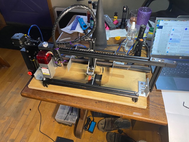
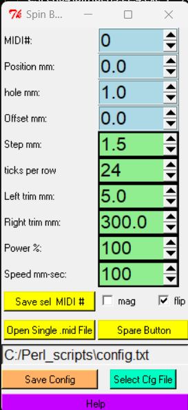
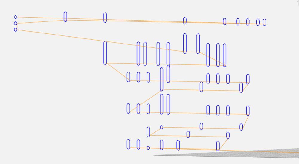
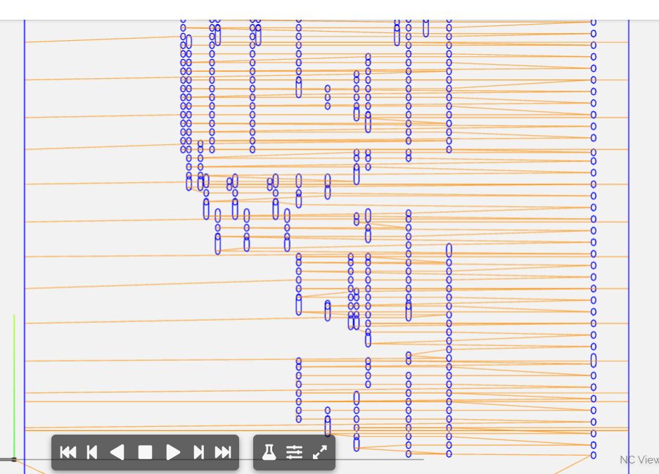
Here are some pictures one of the machine that is currently working. it was made by chopping up a no longer available laser engraver. then one of a piano roll scan midi shown in cakewalk and the gcode file shown in ncviewer. and a screenshot of the gui for the converter program. the image of the midi file does not match the mages of the gcode emulation, i think. the gcode that has lots of G0 m oves has edge trimming but the simpler one that i think might match the midi does not so i included both. there really is a very close agreement no missed rows or any other sloppiness. had to remove one picture since i can only attach 4 so i took out the one without the edge trimming and left the one that does not necessarily match the midi file picture