Since there is conflict, I ran it down.
would indicate that it’s operating as I suggested.
Final truth is the actual wiring manual (or one operating), which probably trumps us all, where I should have looked in the first place…
This link to the TL-3120-PLUS has this illustration…
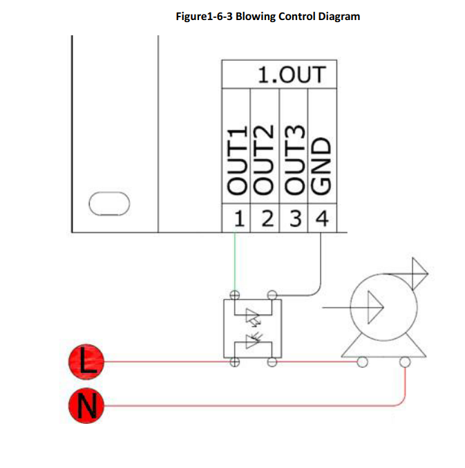

The wiring shows an OUT3, but I don’t see it in any of the device photos. There doesn’t seem to be any kind of current values. They show a ss switch in the diagram, but I have no doubt people hook solenoids to them…
Showing how they did it, quite the opposite of mine and the other ones I worked on in the 70’s.
The drawback of this is now the components become locked into the operating voltage.
I’m sorry I lead you in the wrong direction… I guess I should just keep quiet.
It also makes me wonder about the output going to 0 volts when it in a ‘run’ status.?
Take care, good luck
![]()