Air assist - Delay Relay

I’ve found some negative-trigger delay relays, which should solve the problem, but not in DIN format.

If you have the room, 2 DIN relays
Ruida status -> normal DIN relay coil. Other side of the coil goes to ground. 24V power supply to the N.C. terminal of the normal relay and ground to the N.O. with output from the COM terminal to the S terminal of the delay relay.

Ruida idle -> Status out (high) -> normal relay energized -> no voltage on the COM terminal -> off signal to the delay relay
Ruida active -> Status out (low) -> normal relay de-energized -> 24V on the COM terminal -> on signal to the delay relay + E setting

When the Ruida goes back low->high when it goes idle, it will be seen as a “break” and the delay-on-break will keep the fan going for the specified duration.

Basically the same solution as @Stroonzo just a DIN-ized example of it. The N.O. output of the 600XU is rated 250V/5A, so you can run the fan directly to it.

Quick-n-dirty from an online editor (Circuit Lab):

Ah!
hmm the Delay ON I got working a few days ago as a test… I can give it a try with the N.O. as well… hopefully I find time today/tomorrow to try both your suggestions.

The thing that bothers me (a bit)… is that one need 2 relays to get this functionality working.

Yeah, it’s the normally high output from the Ruida that is causing the grief. It needs to be inverted, and that’s what the other relay is doing. If there is a negative-triggered delay relay in DIN format, it’s a rare beast and the price would probably reflect it.

I have ordered the following controller which will facilitate building a delay off fume extraction without the need of a control relay AND without the need of a contactor:

I saw that one. Where do you see it not needing an inverted input/control relay? I had originally looked at whether a DPDT delay relay would work, and didn’t see a way to make it happen.

Well, I will find out tomorrow! :slight_smile:

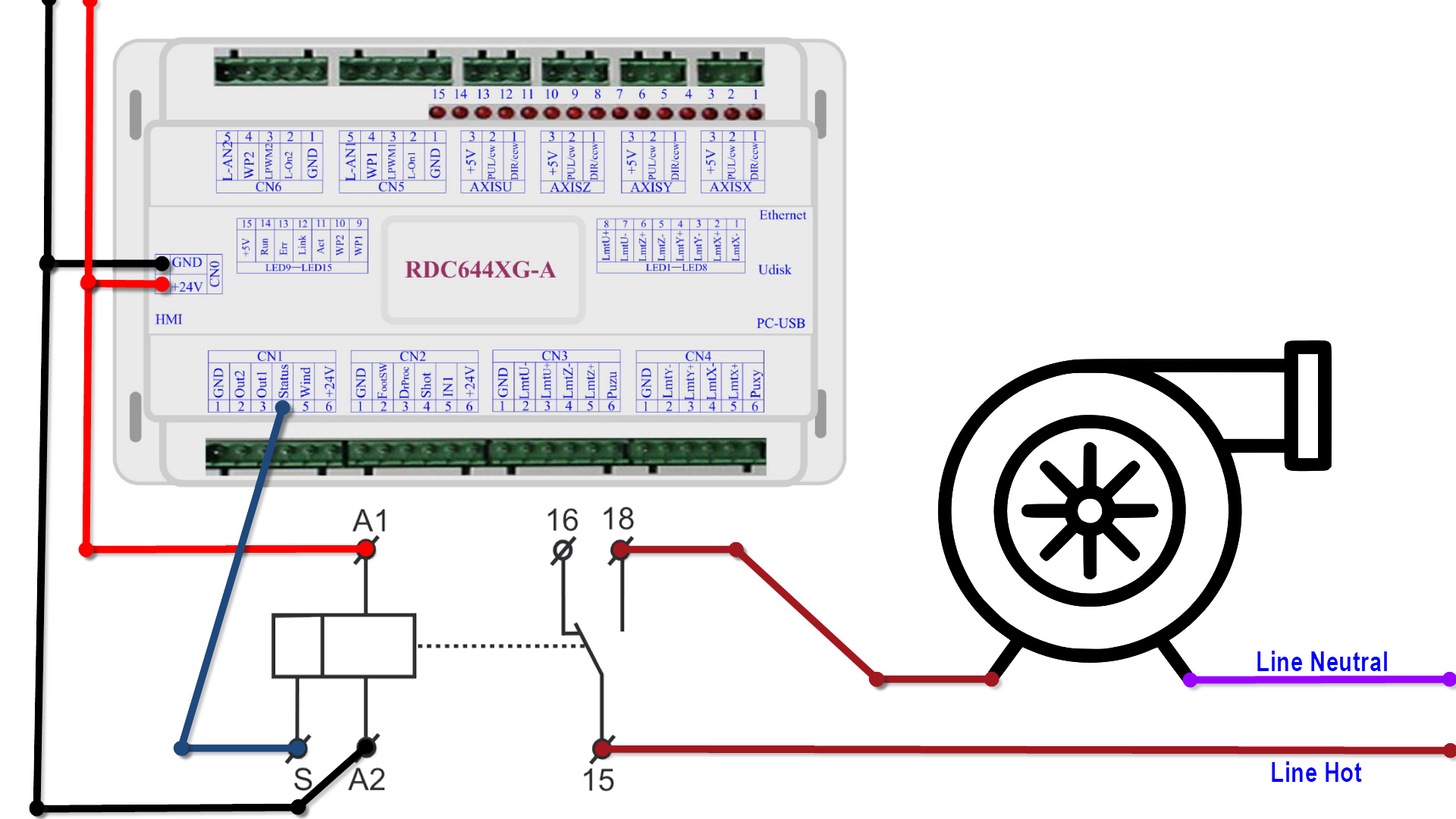
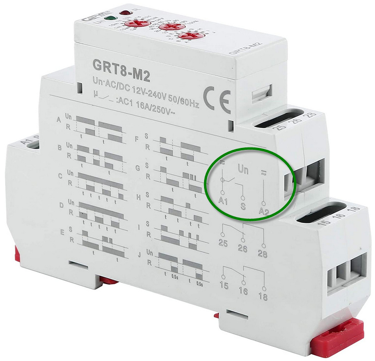
I found no specification on any of the documentation relative to polarity requirement when utilizing DC as the power input source. Therefore, if this is true (and seeing that the control (S) is switched to (A1) then I should be able to create the following:

Now I am very curious if that will work!

Why are these relays so badly documented!?

Ah… I had considered that earlier, but thinking more on whether an AC delay relay could leverage it somehow. I had kinda discarded the idea of using a DC relay in the same way.

Definiltely looking forward to your results. :slight_smile: If it works, I’d check out https://www.amazon.com/GAEYAELE-GRT8-A1-Electronic-DC12-240V-Certificate/dp/B07CGB9XRD/ as less “moving” pieces/complexity.

Because we are looking at a non-standard implementation. “Normal” control signals are active high, and we need active low. I’m sure that a drop-in exact product exists for this, it’s just not-normal therefore rare/expensive. However, @Stroonzo has a solution that is probably “works as designed, but not as intended” :stuck_out_tongue:

The documentation, simplified to the timing diagrams, is actually pretty straight-forward.

Here is my post from last year on the subject of controlling the exhaust blower. I hope this helps.

1 Like

The change here is we want the exahust going to keep going for a defined period after the job is done.
Ideally, have it turn on BEFORE the job begins. :wink:

Although, you could probably make the precognition work by adding a start delay to the first layer a normal part of your workflow…

@rojhan, by tomorrow my setup will:

  • Automatically start the fume extraction upon job start

  • Automatically activate my pneumatic blast gates (both intake and exhaust) upon start up

  • Delay the shut down of the fume extraction

  • Maintain the manual override of the system

Ok, well, I stated my goals at least. :upside_down_face:

@sensor, I will document the wiring for you.

1 Like

Ok, wow. I did it and I love it. I will draw the wiring up tomorrow. How cool is this. I did have to use a relay to convert the negative signal to positive. But no contactor needed. To listen to the extraction start up and blast gates open with the pneumatic mufflers hissing with the job and then run for two minutes before shut down once the job is complete. Wow.

Good job!!
Was it easy to do?

Reading this dialog is like watching my kids in a candy store, I love it. I’m nowhere near this level, however, it’s inspiring so, Thanks!

2 Likes

Here it is drawn in LightBurn. I have a lot more to mine (controlling blast gates as well as a master line switch), but this is the relevant schematic for you (including a manual override switch allowing for independent operation of the fume extractor and bypassing the necessity for the controller signalling).

If you want to download the LightBurn drawing, I have attached it as well. You may want to enable Filled Smooth to view it (Alt+Shift+W).

AutoExtractor.lbrn (1.5 MB)

3 Likes

How awesome!

Thank you for the effort for the schematic!
And as an added bonus: I also found out what the use is of project notes.

Kudos Jeff!

So, playing around with A1/A2 polarity and S didn’t work.:frowning:

At least we’re confirmed that using a helper relay to invert makes it work as expected.

If only I had the time to try the solution today…
Anxious to get it working :slight_smile:

SO I have the setup working somehow but not the way I want to.
the manual override works.
the relay sending a signal to Y1/S/25 works as well.

But… when I put my smart relay on function E (Delay on Break) this happens:
It turns the power on after a break for the set time.
And looking at the picture that is also as designed.

I am afraid that there is none of the 13 functions that does what I ask of it.
I want it to be on all the time when operating plus and as soon as I turn it off… delay the relay break for the set time.