Air assist - Delay Relay

So since I was upgrading to a Reci tube anyway… I ordered the Ultimate Airassist package as well… It is working nice.
But I want more! So instead of the standard relay I bought a programmable relay. I want to delay the power down so that I can attach the fan and give it time to clean the smoke out of the chamber it stops.

However… I am just too stupid to get it working :wink:
The problem is I can turn it on and off, just like a normal relay. I have no idea how to correctly connect the control contact (Y1).

A1 - To Status
A2 - +24v
Y1 - To Status??
As soon as the laser job is done, the relay disconnects so there must be something I am doing wrong.

This is the link to the manual.
https://www.aps-systems.ch/en/600XU.htm

Anyone have any suggestion I can try?

I haven’t used that product, but it looks like you need function “E” delay on break, with the air assist output from the controller/switch going to terminal Y1/25.

Hello Rick,

Thank you for the suggestion. That is something I tried as well.
The wind output to 25/Y1… but no luck.

Draw a pretty picture of the physical wiring you have and the current front-panel settings of the realy?

Delay on break technically means the implementation of preventing re-energizing the circuit for a set time after break. This is often implemented in HVAC systems to prevent compressor lockout and rapid short cycling. So the term is misleading. It usually does not mean “delay breaking the circuit for X amount of time when the circuit is shut off”. BUT, even the control companies are calling both types DoB controls now. So…

The solution is a common component also found in HVAC systems: Fan Delay Timer. These are relatively inexpensive. Amazon Link

Think “DC coil relay” as the thermostat in this drawing. Your controller would open and close that relay (which would then route 24V AC from a simple 24V AC transformer to the ICM control contacts)

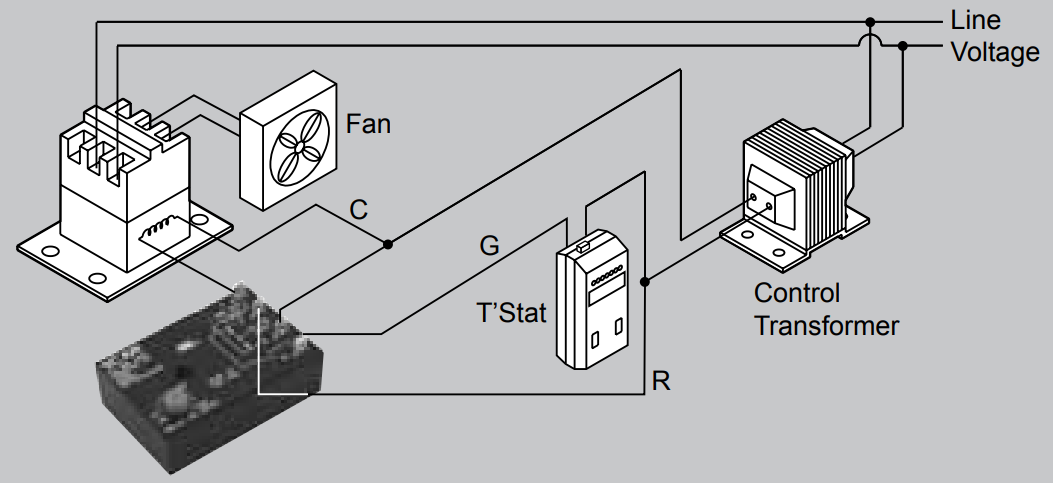
For example, from a Ruida controller, the job status control would output to the DC relay. When the job ran, the relay would close (thermostat ON / fan on). When job was finished (thermostat OFF) the fan delay timer would keep the fume extraction running for the set amount of time.

I should just make a bunch of these up in a clean little package and sell them. :slight_smile:

1 Like

According to the delay on break diagram for the other relay, it behaves as delay-off.

Yes. More often the terms Delay on Make and Delay on Break become ambiguous. Exactly what you guys are doing is all that matters, that is determining the functional use of the component for the required use.

That’s always been “lockout timer” for me. :slight_smile:

Hey Jeff,

Thank you for your response!
After reading your post several times… and looking at below schematic. And not to be stubborn…
‘My’ relay should be able to do the same. (look at Function E)

If I read this diagram correctly… looking at Function: Delay on Break (E)
The Y1 is the control for on/off timer functionality. While the A1 and A2 need to be powered on constantly. (The same as with the ICM 253)

So I would assume that on the Ruida controller either Wind or Status should be connected to the 25 (Y1) while the A1 and A2 make a closed connection with GND and 24+ volt…

Or is my logic wrong here?

Rereading your description, and making the distinction between Ruida “Status” output, and the relay status.

  1. Ruida “Wind” is for Air Assist, not exhaust
  2. Ruida “Status” should probably what you want, but I haven’t used it.
  3. Ground to A2 on the relay
  4. 24V to A1 on the relay
  5. “Status” from Ruida to terminal 25 on the relay
  6. Mains power to COM/pin 15 on the relay, and neutral to the fan
  7. Fan to NO/pin 18 on the relay
  8. Relay function set to E
  9. Time range and duration set with knobs 2 and 3

Going to try that!
Thank you for your time:)

You know, if I were to do the same thing, I’d free up one of the new switches on my front panel… Have 2 extra instead of one. :stuck_out_tongue: Although, I wonder if there is any situation where you’d want to override the exhaust (plus delay). Make the switch an override instead of on/off.

Based on what I have read on your controller, I believe this is what you’re looking for:

Do not run mains into the 600XU timer controller. It is only rated for 5A at 250v. Best to use a contactor as illustrated in my drawing. Also, Status to terminal 25 will not work for a couple of reasons:

  • Status is neg
  • Status is instantaneous (so when job is done, fan would turn off).

You need Status to control a relay as illustrated so the relay contact closes on run job. Then when job stops, the relay is open BUT your controller retards the gate from opening on 18 for your set amount of time.

CAVEAT - I do not have the schematic of this timer (the real internal schematic, so I am not 100% sure of the relationship of the 25: 15, 16, 18. I may have the polarity to the contactor wrong in reference to COM on the timer. (I’d just test it with a ohm meter first to make sure) If I am confused, the contactor would be wired in this manner:

1 Like

Awesome! Very eleborate.

OH! I understand…

You need Status to control a relay as illustrated so the relay contact closes on run job. Then when job stops, the relay is open BUT your controller retards the gate from opening on 18 for your set amount of time.

This sounds indeed like THE solution… makes sense now that I read it. I must have a spare selenoid relay somewhere.

Many thanks for your time! I hope this will do the trick.

Are you sure about the contactor part?
The fan I am using only draws 0.29 A @ max at 220v

Do the Ruida outputs pull down to ground or up to 24V?- Answered my own question. I forgot that they pulled to ground with a common 24V. My switches have their own source of power, but my air assist is directly wired to the Status output.

I wonder if you could use a delay-on (instead of delay-off) and use the NC instead of the NO contacts to achieve the same behavior without the need of an additional relay. I just hurt my brain writing that, so I need to draw it out…

Working backwards, the simplest solution would be a device that provides:

You need the N.O. contacts because you don’t want power going to the fan if the system is off. As long as Ruida pulls status low (active) and for “T” time after, you want the relay to be energized and the N.O. contacts closed/on.

Or, something to invert the Ruida output and “E”, which is what the additional relay does.

I’ve found some negative-trigger delay relays, which should solve the problem, but not in DIN format.

If you have the room, 2 DIN relays
Ruida status -> normal DIN relay coil. Other side of the coil goes to ground. 24V power supply to the N.C. terminal of the normal relay and ground to the N.O. with output from the COM terminal to the S terminal of the delay relay.

Ruida idle -> Status out (high) -> normal relay energized -> no voltage on the COM terminal -> off signal to the delay relay
Ruida active -> Status out (low) -> normal relay de-energized -> 24V on the COM terminal -> on signal to the delay relay + E setting

When the Ruida goes back low->high when it goes idle, it will be seen as a “break” and the delay-on-break will keep the fan going for the specified duration.

Basically the same solution as @Stroonzo just a DIN-ized example of it. The N.O. output of the 600XU is rated 250V/5A, so you can run the fan directly to it.

Quick-n-dirty from an online editor (Circuit Lab):

Ah!
hmm the Delay ON I got working a few days ago as a test… I can give it a try with the N.O. as well… hopefully I find time today/tomorrow to try both your suggestions.

The thing that bothers me (a bit)… is that one need 2 relays to get this functionality working.

Yeah, it’s the normally high output from the Ruida that is causing the grief. It needs to be inverted, and that’s what the other relay is doing. If there is a negative-triggered delay relay in DIN format, it’s a rare beast and the price would probably reflect it.

I have ordered the following controller which will facilitate building a delay off fume extraction without the need of a control relay AND without the need of a contactor: