at the output of the card I have 3v which means that the relay is in operation, the voltage at the output of the card must be
0 v for the relay to change position. But no command changes the board voltage
Those are valid GRBL g-code so “Ok” is a fine response. The question then is what the controller does with the commands. Meaning does the hardware properly react to the command and expose a voltage shift. Did you measure this.
Note that LightBurn is already generating M8 and M9 commands in its g-code so you would not need to enter this in start/stop. Also, in the previously linked Topic they mention using M7 instead of M8 to enable air assist.
I have no change in the card with these commands the voltage is always 3v, maybe the firmware does not allow it.
Still no response from the manufacturer.
I’d suggest measuring voltage for all the unknown pins on the board both during rest and with M7 and M8 enabled. It’s possible that it’s getting exposed elsewhere.
the SCL output must not work with the M7, M8 or M9 commands. I don’t know how the firmware was coded. I don’t know how to find what it works with, if it works other than always on (+3v)
I’m suggesting to test the other pins. It’s possible that M7 or M8 is affecting voltage on another pin that’s not currently apparent.
I’d suggest probing the other pins on the I2C port and then the runback button and touch screen interface ports.
I’ve been following along… but I question the wiring…
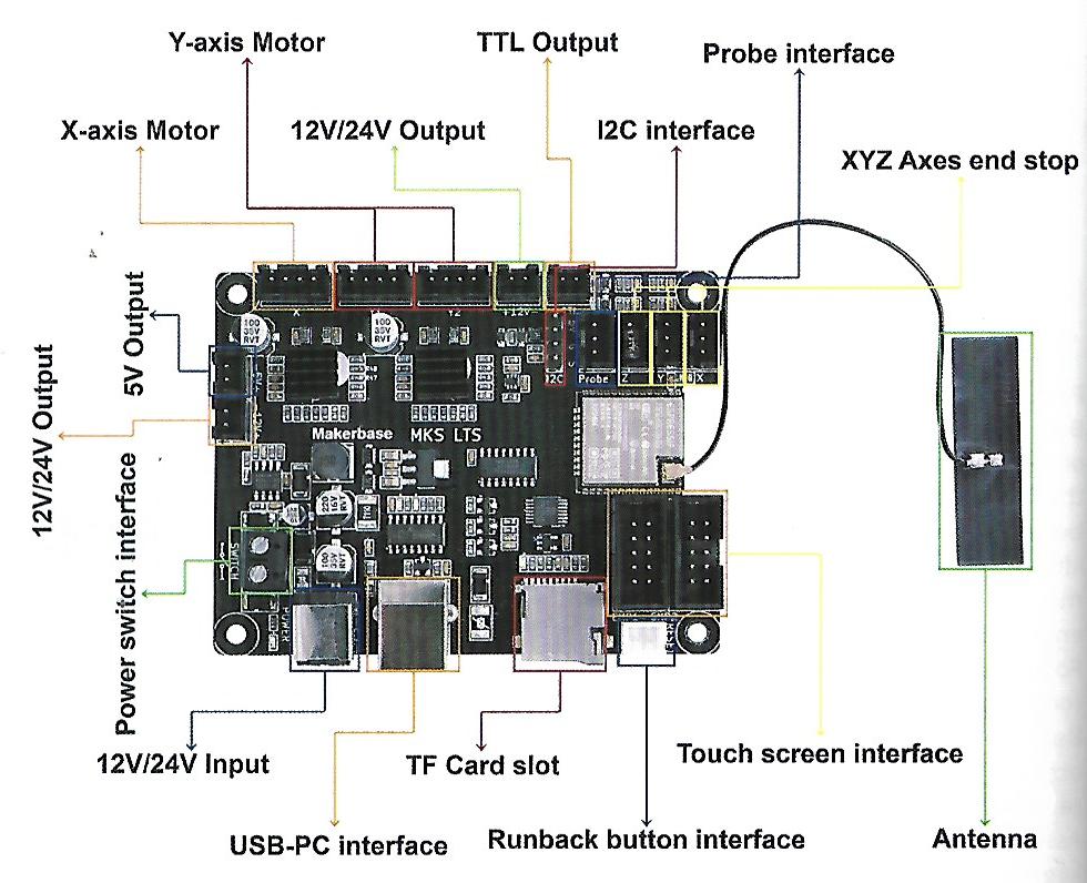
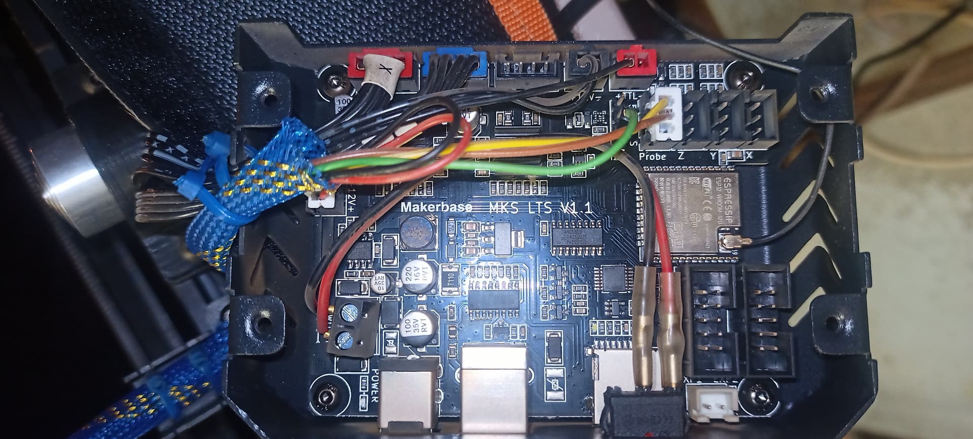
This is a photo of my MKS DCS32 controller… the label is very clear to as to what’s there.
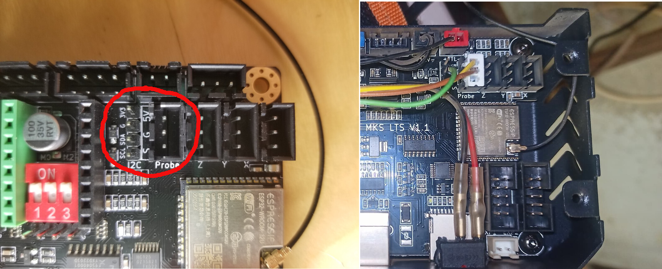
I would think the green wire would connect to SCL. Wouldn’t that be the one on the bottom?
Even the one in the link he posted is wired that way…
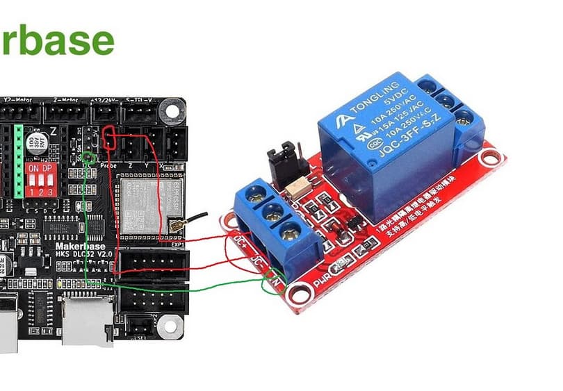
I think he has the relay wired to the i2c ground connection… configured like this the relay should be inactive…
I would check on the wisdom of using the SCL output to directly drive a relay or in this case an optical isolation device… I don’t know and the data sheet isn’t likely to mention it, since the specifications keep the current low.
Here is the schematic of mine… looks like it’s just i/o 4 No idea of how much current they will sink… maybe there is a buffer in between?
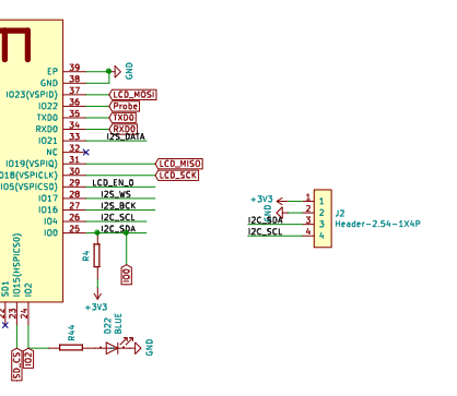
They also do not supply current, they pull the line low when active.
![]()
you can’t see it well on my photo but I put the wire to the bottom terminal, the connection is well done as in the picture
you can’t see it well on my photo but I put the wire to the bottom terminal, the connection is well done as in the picture
tomorrow I will take measurements on the other connectors
jk wilborn is that on your motherboard when it is just powered, you have a voltage of 3v between scl and gnd?
Mine is still in the box, haven’t put it into a machine yet…
Measuring the open collector output of an i2c device isn’t going to do much, as by design they only pull the signal low… I’m guessing that it’s just floating there…
If I get a few I’ll hook it up and see what it will do on it’s own…
![]()
I did power mine up and it reads 0 volts from ground to the SLC pin. I have the standard cnc firmware in it, not for a laser…
Take that back I loaded a newer version and I get a lot of initial information, but can’t ask it anything…
![]()
Ok thank you, at rest 0V, which I find logical, me on my card I have 3v.
I will do research on the other terminals otherwise I will change the motherboard.
It sounds like the output is on, maybe it’s not hardware…?
What firmware is loaded?
![]()
I don’t know what firmware is on the motherboard. Is there a way to find out?
When you plug it in and it connects, it should display it’s firmware on the console in lightburn…
![]()
ok i’m looking at this
twotrees just replied to me: Dear,
the firmware of TTS mainboard doesn’t support using M7,M9 command,but DLC 32 mainboard could do it(its publish firmware could support it)
Regards
I then asked if he could change the firmware.
This afternoon I will look at the firmware version, I wondered if it would support the firmware of a DLC32.
DLC32 uses GRBL_ESP32 for its firmware.
While the LTS and DLC32 boards are similar it looks like they’re not quite electronically the same. You can see some dialogue about this in FluidNC discussion (FluidNC is the successor to GRBL_ESP32):
Feature: Configuration for MKS LTS 1.1 · Issue #857 · bdring/FluidNC · GitHub
It’s not clear from the thread if everything ends up getting working but it looks like it have.