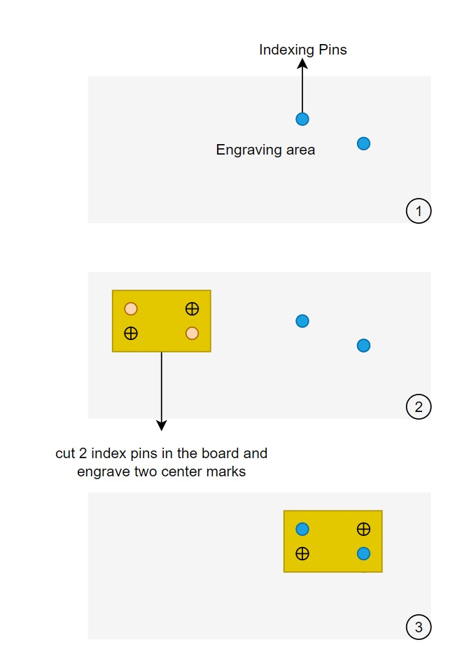
Hi, I have made a jig that consist in two pins attached to the machine. The first step that I do it’s cut two holes and engrave two center marks in all boards that I will be engraving. After that I put the board fixed in the two pins. Now I would like to move the drawing in Lightburn the way that I can align center marks with laser. That way the pins will be perfectly align with the conter of the drawing, and if it’s necessary to flip the board the center continue in same place.
I know that I can do that using print and cut. However what I want to do it’s move the drawing in Lightburn. That way I can align the center of drawing with pins in machine. And any time that I need to put
Another board, I know that the center it’s in center of pins to.
I include the relevant jig geometry directly in the design as a locked tool layer.
But how can I relocate the design in Lightburn with the center marks in jig?
Do you work in absolute coordinates? That’s the key to making jigs work. As well as having a repeatable homing setup.
You know the centers relative to your workspace, correct? Draw the pins exactly as they are, using the absolute coordinates, include a square outline that you can dock to 0,0. Sove this as an art file. Then you can drag it into any project at will and simply dock to the workspace origin (0,0). If unsure or wanting to validate pin location, you can do an initial drawing of just the pins on a normal layer and run them as a job with minimum power (1% or whatever). Adjust the drawing until this job perfectly overlays the jig. Then change it to a tool layer and save as art.
So attached an image. How can I use the centre marks to align perfectly the drawing in Lightburn and in the table?
The pins are already fixed so I have to adjust in Lightburn. Do you have any function for that? It’s necessary the two marks because I can have some rotation when I put the jig.
The objective of that it’s to after engrave in one side, flip the board and engrave and cut in the other side.
I’ll try to step through the way I do this on my Ruida, maybe that will help you with your setup.
I suggest you save any templates, locally, a local physical back along with a copy to something like Google drive. it’s in three places all separated. If you loose these they can be very difficult to re-create. I do this with all of my templates, which is quite a few.
First step is to draw out the hole pattern… it’s along the edge in red… it was initially used to mark the metal table for drilling on the drill press.
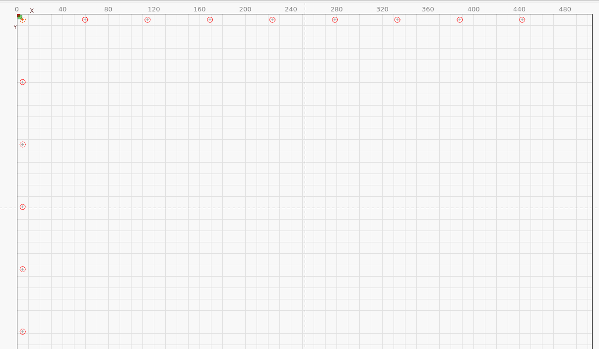
Save this file separately as you can import it into any future jig. Mine are just saved in a template directory as hole-pattern-[machine].
This is used to make alignment holes in the actual to be jig. I use M5 screw/nut as the pins for alignment.
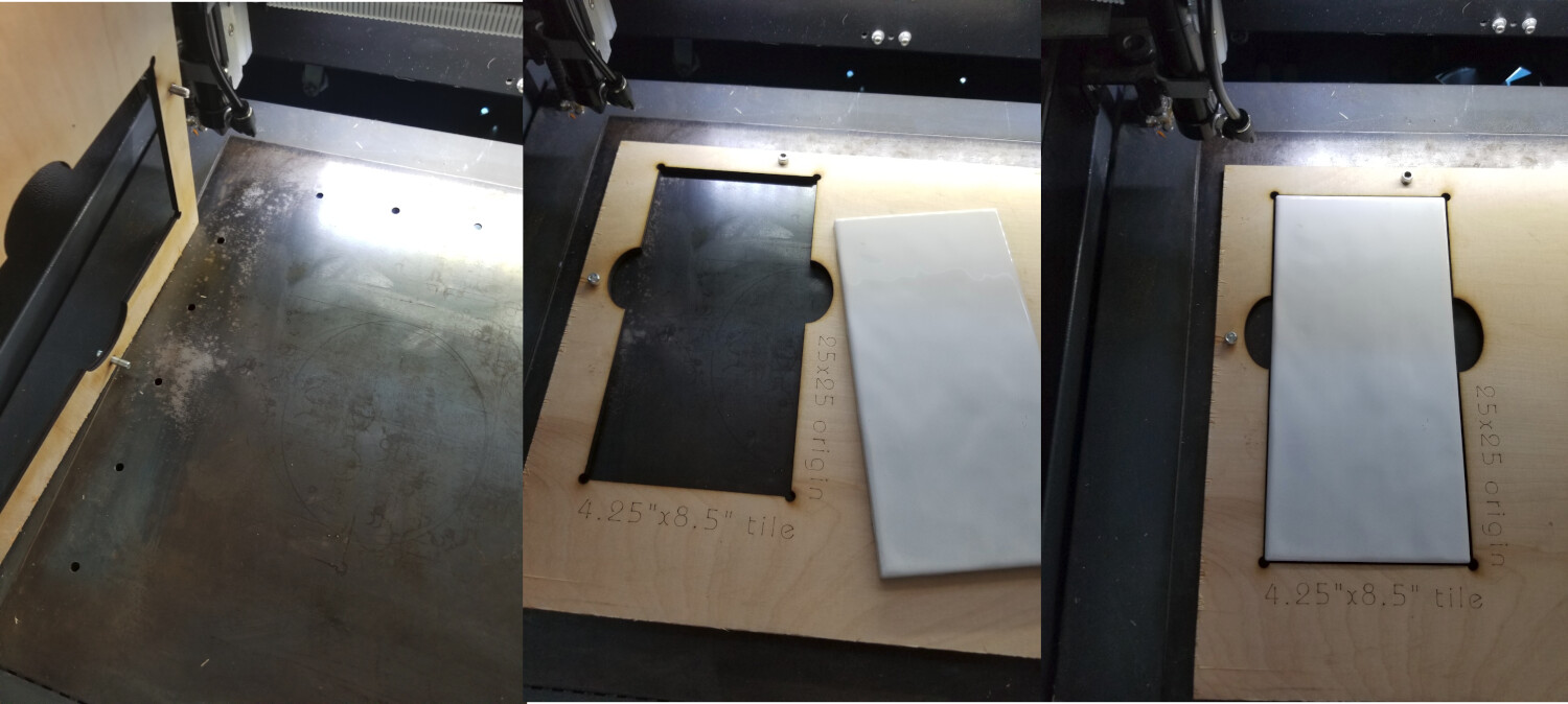
I add the pins and place the material back on the table… Now everything you cut/engrave is aligned to the machine.
Create a new project file, with an identifiable name.
Create the jig artwork. This is a 4.25x8.5" porcelain tile.
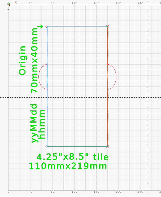
There are three layers, one for the text, a tool layer and a cut layer. The tool layer is the size of the object. The cut layer was created by duplicating the tool layer and adjusting it for clearance or area to be engraved, if needed.
Since all of this was done as absolute coordinates, the text and tile hole will be aligned to the machine because the pins ensure it’s placement. I do the text and cut out the tile hole.
I put as much information as needed on the template. Origin is specified on the jig, I can enter this, the head will be positioned and I can press origin on the Ruida console… I commonly have start from set to user origin… This is saved even if I need to reset the machine. I can just as easily run in absolute coordinate mode. I prefer the head to end up somewhere reasonable ![]()
I have finger holes for my fat fingers to get a grip on the object. Most of this tile has pointed corners that can interfere with alignment. I have open areas on each corner to handle odd corners that occur with tile.
I’ve found it handy to include the date/time of the jigs creation.
You can use a tool layer with the same origin and easily place the artwork within this tool layer. There are a multitude of artwork alignment options after the jig is cut…
With the circular slate coasters, the engraving area is smaller than the object size.

These photos took place over time as I was learning how to do this… so not everything matches up exactly…
Does any of this make sense or help?
![]()
This topic was automatically closed after 30 days. New replies are no longer allowed.