Aligning two workpieces on multiple machines

Hello All,

I am running into a problem that I need help with.
I use two different machines:

  • Atomstack for burning texts.
  • Stepcraft M1000 for milling the file.

Example: Attached bear. The black lines must be milled out with the stepcraft.
But the blue lines and the text have to be burned in with the atomstack.

How can I align both workpieces so precisely on two different machines?

Thanks in advance.

Remco

There are a couple of ways… the real question is what kind of precision do you need?

The first is the tried and true was of cutting out a jig to hold the item in the position required. This is the same as using some kind of alignment pins…

I followed this on one of my projects… On the cnc with the scrapboard I drilled two locating holes at the 10mmx10mm and and at the 120mmx120mm. Inserted pins…

Did the same with the table on the laser. I mark where the holes need to be in the material on the laser, drill them and use the same absolute coordinates for both machines…


Similar idea…

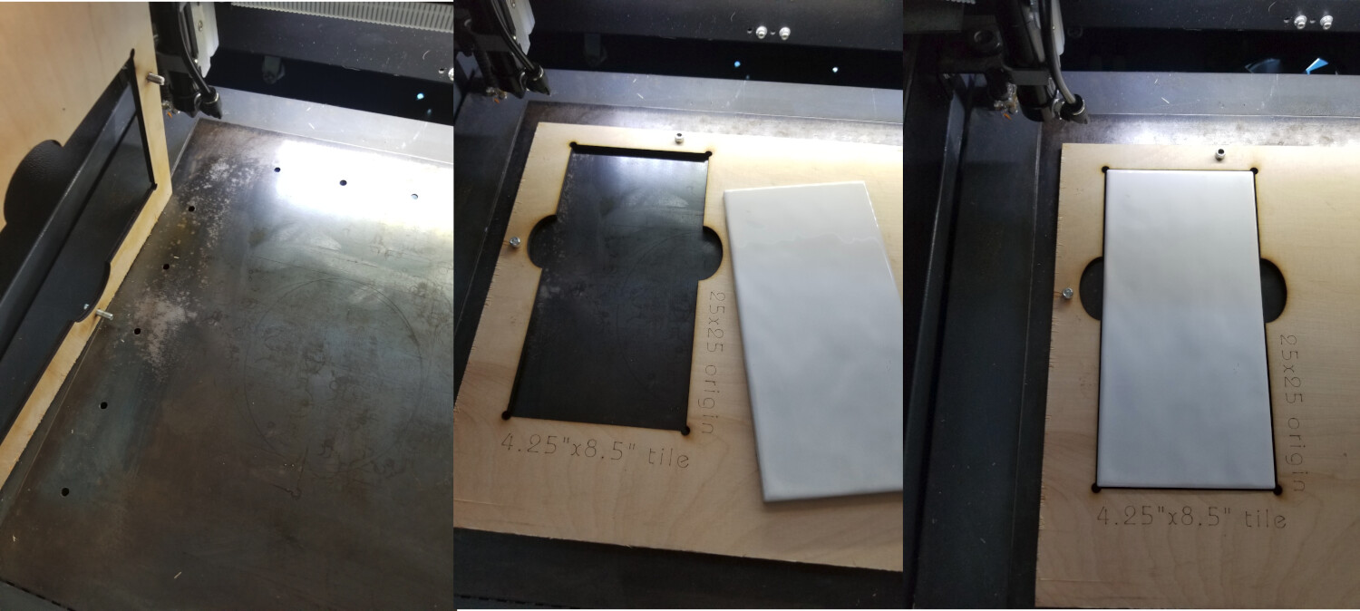
You can also make a cutout to hold the piece that somehow keys to your laser/mill. That’s how these are made for porcelain tile… I use the holes in the table for alignment pins… the precision here is within a couple of mm, fine for duplicating tiles…


If you have a camera on the laser, you can use cut & print. Mill it first then use cut & print to align the laser…

Good luck

:smile_cat:

Are you cutting the bear out completely?

Have a look at the Print and Cut feature in the Docs to see if it will work for you.

The problem with the mill is you won’t be able to line up your laser with a feature on the bear because of the Kerf of the tool - unless you have offset your cuts by half the tool-width to leave an on-size corner to align Print and Cut with. If you have the latitude to cut registration marks on the mill and can drop an insert in the hole (with a pinhole in the center) to pick up the center with the laser, Print and Cut might work well for you.

Urban Legend, I assure you. :wink:
Check out the video in the docs.

Thank you for your responses. I’m going to get started with the print and cut function. However, I can’t get my machine properly set to x 0 and y 0. When I turn on the machine and start up lightburn, the laser goes home. But then it continues to search for the zero point for a while, even if it cannot go any further.

How do I get the machine set so that the current position it is in is 0? I have already tried turning off the machine → restarting lightburn. Then it says X = 0 and Y = 0. But as soon as I click home, the laser starts smashing the frame again.

My bed size is 800x400

Video: video 2023 07 02 13 21 10 - YouTube

Output:
Waiting for connection…

[MSG:Local access point Engraver_8396 started, 192.168.4.1]
[MSG:HTTP Started]
[MSG:TELNET Started 8080]
[MSG:‘$H’|‘$X’ to unlock]
Grbl 1.1h [‘$’ for help]
[MSG:‘$H’|‘$X’ to unlock]
[MSG:Caution: Unlocked]
ok
ok
ok
[VER:1.1h.2022070601:]
[OPT:VZ,15,128]
Target buffer size found
ok
<Idle|WPos:10.000,-10.000,0.000|FS:0,0|Pn:P|WCO:-10.000,10.000,0.000>
ok
$i
[VER:1.1h.2022070601:]
[OPT:VZ,15,128]
Target buffer size found
ok
$$
$0=10
$1=25
$2=0
$3=0
$4=0
$5=1
$6=0
$10=0
$11=0.010
$12=0.002
$13=0
$20=1
$21=1
$22=1
$23=3
$24=300.000
$25=3000.000
$26=250.000
$27=1.000
$30=1000.000
$31=0.000
$32=1
$37=0
$40=2
$100=80.000
$101=80.000
$102=80.000
$103=100.000
$104=100.000
$105=100.000
$110=6000.000
$111=6000.000
$112=6000.000
$113=1000.000
$114=1000.000
$115=1000.000
$120=1000.000
$121=1000.000
$122=1000.000
$123=200.000
$124=200.000
$125=200.000
$130=400.000
$131=800.000
$132=200.000
$133=300.000
$134=300.000
$135=300.000
ok
$#
[G54:-10.000,10.000,0.000]
[G55:0.000,0.000,0.000]
[G56:0.000,0.000,0.000]
[G57:0.000,0.000,0.000]
[G58:0.000,0.000,0.000]
[G59:0.000,0.000,0.000]
[G28:0.000,0.000,0.000]
[G30:0.000,0.000,0.000]
[G92:0.000,0.000,0.000]
[TLO:0.000]
[PRB:0.000,0.000,0.000:0]
ok

On your Engraver, is X-Axis 400mm and Y axis 800mm? If this was measured directly from rail to rail you will have to subtract the width of the moving part (half from one end of the Axis, and the other half from the other end of the axis.

If the X-Axis is 800mm and the Y-Axis is 400 you’ll want to swap the values for 130 & 131.

We should test the switches.

In the Console window, type the following:
?
then press Enter.
then reach over, engage and hold (or tape) the X-Axis limit switch in that position and type:
?
then press Enter.
then release the X-Axis switch and engage and hold the Y-Axis limit switch in that position and type:
?
then press Enter.

You should have three almost identical but different reports. Please copy and paste them into a reply here.

I didn’t see the error message that a failed switch usually makes.

This topic was automatically closed 30 days after the last reply. New replies are no longer allowed.