I am trying to align my camera, I follow the steps but the alignment never seems to be accurate 1.73mm of inaccuracy. I zoom in and get as accurate to the cross hairs as possible when aligning things but nothing seem to get it spot on. What can I do to improve my results?
If you can’t get exact alignment with the camera alignment tool alone then use the controls in the Camera window to make fine adjustments to the alignment.
Thank you, I have played with them but seem to have little success over the entirety of the bed. I can certainly get one spot dead on but when I move to the other side of the bed it’s off. Do you know of a proper way to calibrate this using this manual adjustment?
This implies that you have a fundamental problem with either your calibration or your initial alignment.
Are you testing your alignment at the same material height as you did your initial camera alignment? If not, this might be the source of any variance. Distance from camera is significant due to perspective. If you haven’t already, make sure initial alignment and subsequent use of the camera is all from the same distance to camera.
As for calibration, what type of scores did you get? Do you have an unusually wide angle lens? If you have extremely high distortion or inconsistent distortion of the lens this can cause calibration issues. Did you paste the calibration pattern to a stiff flat board like MDF, glass, or other known flat surface? Taping or simply resting a piece of paper to the bed can leave ripples or slight curls in the paper that will result in additional distortion.
A couple of other things to look at:
Is the lens securely attached to the camera? Is it possible the lens is wobbling around slightly in the camera? If so, this can cause some issues with focus or alignment.
Is your camera mounted in a way to guarantee repeatable location? Even a small change in location can throw off alignment.
I am using the same height for alignment and testing, they are one right after the other.
I am using a wide angle lens for sure 170 degree
My calibration is attached to the same material that I am testing on
The camera is affixed firmly as is the lens, I have even shimmed the lid to ensure no slop.
During testing and calibration I did not move or lift the lid to rule it out.
When I align the pattern one thing I note is the patter zoomed in is much larger than the cross hair which forces me to put it in what I guessing is the absolute middle.
One thing if the error was correctable by X & Y adjustments I would understand but it’s not, not even close and the error is all over the place based on what corner of the bed you are on.
Hard to say for sure but you may want to spend some time to see if you can get calibration really dialed in, especially with that lens. Lower scores would be nice.
How much of the camera capture is filled by the bed? Can you take a screenshot of LightBurn?
Can you elaborate on this? How are you testing this on the same material as the calibration?
Sounds like motion can be ruled out for the cause of the alignment changes. One note, calibration does not require the camera not move. This is only required during alignment and for every subsequent camera operation.
Didn’t quite follow this. Can you further elaborate what’s happening here?
Can you quantify in what way the alignment is off? If the variance scales differently at different corners then very likely an issue with calibration more than alignment. You need to try to get as much distortion out of the capture as possible.
Also, under normal circumstances you should be able to get placement accuracy to within 1mm or so.
Another consideration, when you burn your alignment markers have you scaled it to fill as much of the bed as possible? What are you burning to?
You and the instructions suggest mounting the cal sheet to a flat surface, this has been done by affixing it to a flat sheet of 3mm wood the same material the adjustment material is lazed into.
As to camera movement I try to limit that as to rule it out as part of the issues.
So the lazed pattern when zoomed in is may times larger then the cross hairs I am to align to.
I am unsure when you discuss removal of the distortion. There is no setting for this, according to the directions you simply put the test piece where it ask then hit the test. I keep doing it over and over until I feel I have the lowest number I can get it to give me.
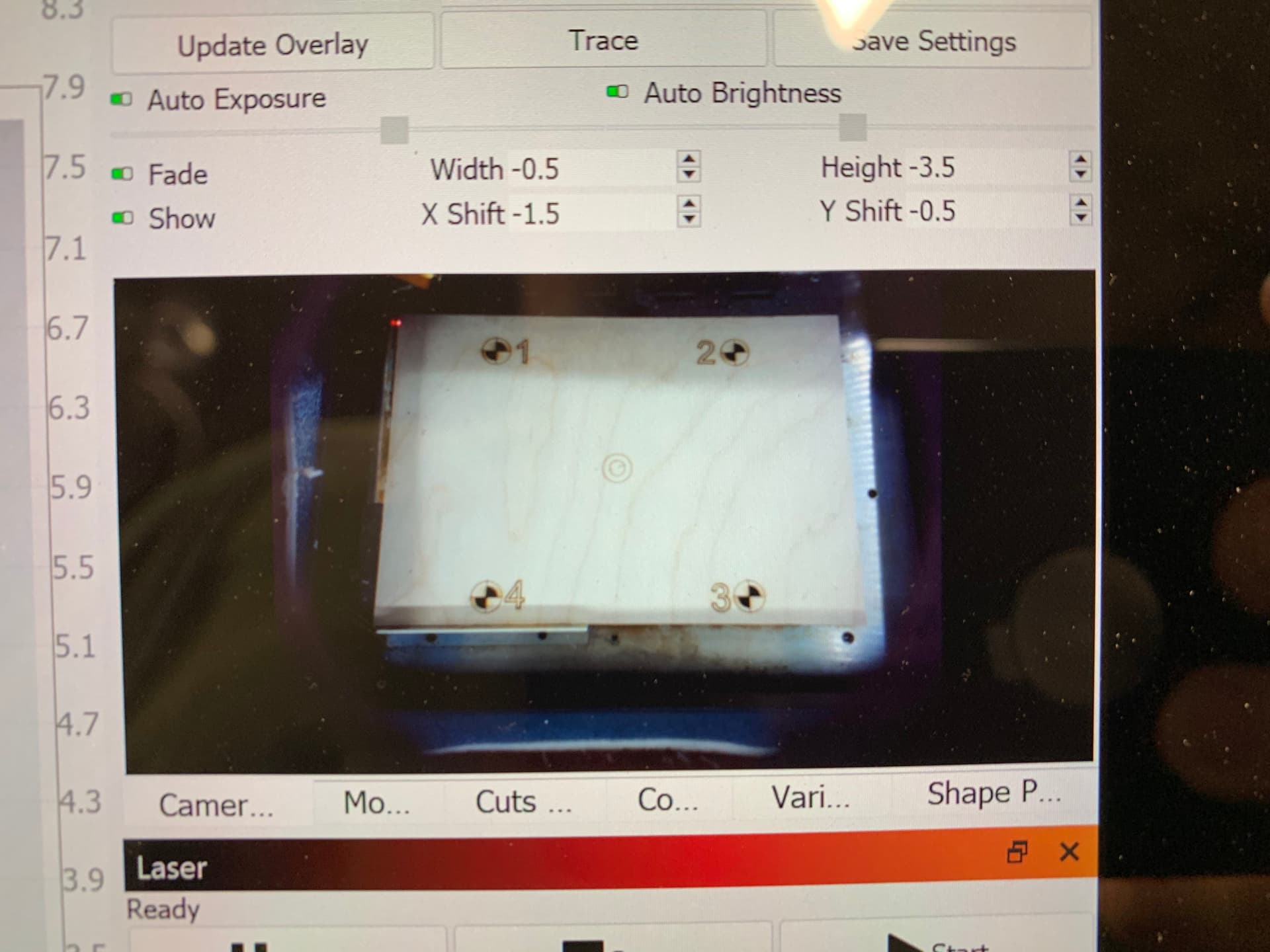
No I have not scaled it but as you will see in the pic it fills a fair bit of the bed. Both the cal and the alignment fixtures fill the bed as my bed is small
If you’ve pasted the whole surface down then that’s about as good as you’ll get.
How are you zooming in? And the cross-hairs are your laser light or you’re saying the actual engraved crosshair alignment target?
Yes. There is no setting. I mean that all the proper setup is necessary to minimize distortion. This includes the pasting of the pattern to a known flat surface. See if you can improve lighting and position to get scores under .3. Ideally this would be under .2.
Can’t quite tell from the picture… is the wood base covering almost the entire bed (metallic border)? If so, the bed is taking a fairly small portion of the camera capture and is off-center. I suspect that means the calibration process is doing more correction on the top portion of the image than it is toward the center.
When you Update overlay, do the vertical and horizontal edges of the material appear perfectly straight and at right angles?
With your manual adjustments how much variance are you getting now? Is it less than the original 1.73 mm? If you’re under 1 mm now this may be about as good as you get with your setup.
When you do an alignment you can zoom in using the zoom button. As to the cross hairs they are the ones provided during the alignment. I don’t know how else to describe them, they are part of the software like the zoom button???
My lighting inside is very bright (360 degree high intensity LEDs) and I have even lined the internal surfaces with polished aluminum. The scores are the best possible without knowing factors that can improve the score. I have redone the test 20x just to see improvement. In some cases I have to move the dots just to even get it to see them and score me at all. The instructions say do X what they don’t say is how to improve the result of X if you do X and get a poor results.
I didn’t know that the camera needed to be in the exact center of the bed? I have seen some that have it off set to the front of their laser. As to camera a distance. If I move it closer I will not get it to cal at all, in fact back would be better to get better results. I would love it closer indeed.
1mm is never going to work for me. I need repeatability and accuracy, that’s why I invested in the camera and have been taking the time to get it sorted. I have seen people stop a project move the piece and restart allowing a larger project to be made.
I want to say thank you for all the time and effort you have invested into help me, it is very much appreciated.
Got it. I didn’t realize you were talking about the actual step in the alignment process. I think what you’re describing is fine.
It needn’t be. But if you’re working with an extreme fisheye lens the farther from center will require more correction. In a perfect world it wouldn’t matter.
Are you adjusting the focus appropriately?
Yeah. This can be frustrating. Even slight variances in shadows can affect the score. You might have better luck with this outside of the machine but hard to say.
If that’s the case then camera positioning may not be the right tool for your needs. I think general expectations for this from what I’ve seen is roughly sub 1mm positioning accuracy in a good case. I’d like to hear others experience with this though.
I don’t know of anyone relying on camera positioning alone for Print & Cut but I may be wrong. The cases I know of people are using visible lasers to do this. To do Print & Cut well you’d really need to be in the .2-.3mm accuracy range or better or else you’ll get a fairly prominent seam, depending on material.
You can see Oz using a visible laser to align the mermaid for the segmented P&C example in this video:
I really appreciate your feed back. While I have a visible laser it is not accurate enough for that activity, thus was my desire from the camera. Thanks again for being a fountain of wonderful information it was really helpful.
Glad to provide perspective where I can. Wish this resulted in a better outcome for you.
I’ll trust that people who are doing this with a similar use case to your own speak up. I’m just not familiar with anyone working to those tolerances with the camera alone.
I wish I had a better way to keep tight tolerances. I am baffled to what the use of the camera is for if it is not accurate. I am also wondering why someone from Lightburn has not responded to this? It would be nice to understand why the camera software is so inaccurate and or what I can do to fix this to make it accurate.
Again thanks for all your help, I will keep messing with the cal to see if I can improve it.
It is accurate actually… but to a certain tolerance. The general use case I’ve seen for the camera is rough job locating, image trace… I think I saw someone using it for a rough print & cut (not extended cut).
I suggest you articulate the precision level you’re looking for. Sounds like you’re looking for placement accuracy to within .1-.2 mm. Will help people get up to speed quickly on what you’re looking for and to see if this is possible.
Let’s see if @Rick or some other LB folks can provide some additional insight.
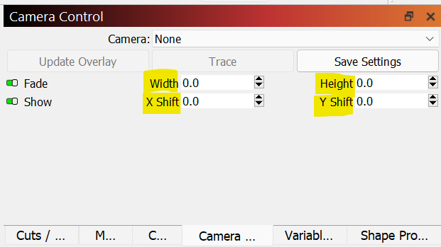
The width and heught buttons are used to adjust the scale. using two points a known distance apart, adjust width and or height until both are spot on. Then use the shift x & y to get the position correct.
Unfortunately when you make test marks in all the corners of the bed the error is not equal nor in the same quadrant relative to the mark. The error if plotted might look like 1,1 1,-3 -2,0 -3,-5 note that was just an example not reality. If that makes since?
No clue as I really have no tangible way to measure the dot size. The important factor is that things line up. I don’t care if the dot is 5mm or .1mm I would like when I make a cross with 2 lines that the lased results are where the drawn lines are.
")