When you’re in a hole…
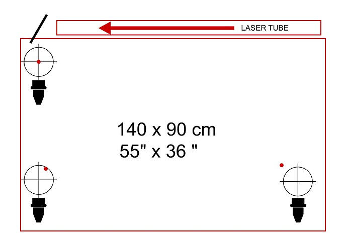
I’ve been running an OMTech 130w for a few months, cutting 3mm MDF and 5mm ply with no real problems. I last did the mirror alignment a couple of months ago - all good, but after maybe 2 weeks the cuts furthest from the laser started to deteriorate (the work area is 140x90cm). I decided to realign the mirrors again today, starting with mirror 1 then 2 and 3. After alignment I tried a test cut and had no visible laser anywhere. Turns out that the laser is dead centre on mirror 1 and it hits dead centre on mirror 2 when it’s moved close to mirror 1 but once the laser head moves away from top left position it loses alignment until the laser doesn’t even get inside the circular opening of the mirror. So I can align the mirror fine but once they move along their axes they lose alignment. I don’t want to make this worse by undoing rails without asking you guys what you think. I’ve checked that nothing’s loose, from the tube to the rails, mirror brackets etc. Where do I go from here? any help would be really appreciated.
With a target in m2 (mirror 2) mark it closest to m1… if m1 is adjusted correctly it should print in the center of m2.
Moving to furthest from m1, adjust m1 to converge on the closest mark. Changing m1 may change where it marks on m1, so you may need to repeat the procedure.
Repeat until both ends converge at/on the same spot…
Is this working?
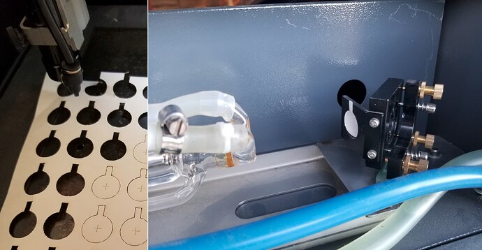
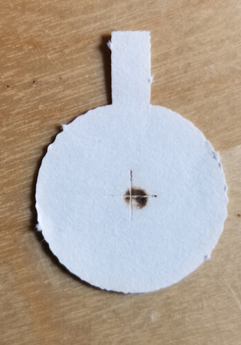
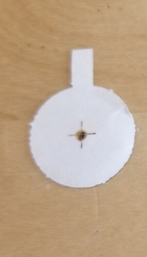
It may be the tube going out of TEM00 mode. I check it like this… it’s the right photo…
![]()
Thanks for the reply Jack. If I understand you correctly, yes I first centred the tube to M1 and then M2 closest to M1. However when M2 moves along the Y axis it’s way off target, if I re-center it there, it’s way off when it returns to close to M1. The first time I did the alignment I didn’t have this movement along the axes. I read the link re TEM00 - it’s pretty technical - I didn’t understand what the process is for checking or correcting.
When a tube lases, it has to resonate properly with the beam going back and forth… As the tube ages, which can occur suddenly, it no longer resonates properly and produces other patters in the beam indicating a gas problem…
All you are doing is looking at the resultant burn to see if the output is a Gaussian type power curve… although too dark the idea is to have a TEM00 nothing else… this is worst case…
This is a graph of proper power distribution… it should be darker in the center as this is where the most energy exists in the beam.
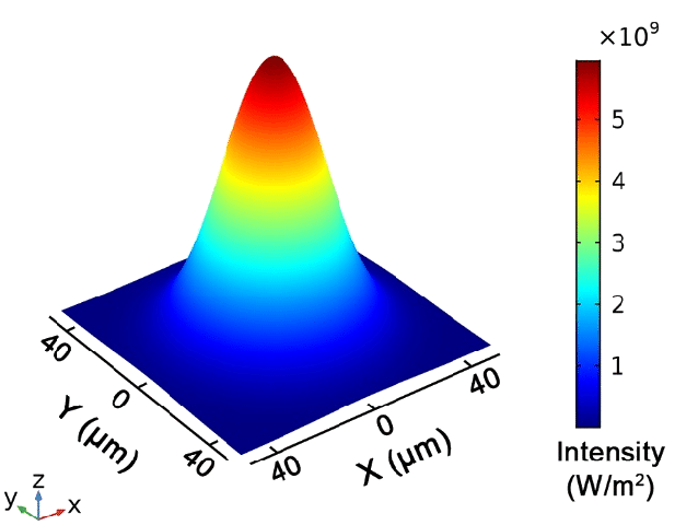
These are the TEM00 state and a failure… it can be many patterns, we want the TEM00 type output… It’s really a bit dark, so I’d go for less pulse time or duration.
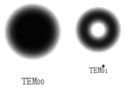
This is when mine failed…
The correction in this is usually a tube replacement ![]()
Check it and see what you get… post a photo of the results for us to examine.
Alignment required you to move m2 repeatably until the burn spots coincide.
Did you move m1 to be as centered as possible on m2 when they are as close as possible?
IR from a co2 is not visible… wouldn’t expect it … if you mean something else, please explain.
I think it’s not aligned correctly… until we determine if it’s resonating, It sound rather like you’re just having an issue with alignment…
Let me know what you get from m1 test.
If all else fails, try moving the mark onto m2 via m1’s adjustment when it’s max distance from m1 and see how it looks when you bring m2 to it’s closest position.
Did you move the physical mount of m1 or did you just use the knobs for adjusting?
![]()
Right, I understand the TEM00 issue, thanks for the explanation Jack. I’m pretty sure the burn is a clean circle, but I’ll re-check.
I agree that it’s more likely I’m doing something wrong in the alignment process.
Did you move the physical mount of m1 or did you just use the knobs for adjusting?
I’ve only adjusted the mirrors with the 3 knobs.
I’ll follow your alignment procedure and come back with the results - I’m on Europe time so it’ll be tomorrow for you.
Thanks for your comments and support.
Not a problem…
What most people experience is that they try and adjust for center at the maximum distance.
You have to make the maximum distance spot coincide with the spot that is closest. It may not be in the absolute center…
This is a video by Russ Sadler that details an alignment… wouldn’t hurt to review it…
He has made a bunch of these videos on different lasers, mostly co2…
I have a couple of his designs such as his head on my laser…
Good luck
![]()
Update - I’ve watched the excellent Russ Sadler video and today followed his procedure. It’s helped a lot but I’m not there yet. I spent a few hours just on aligning M1-M2 today and, with the tube centred on M1, the best compromise I can achieve on M1-M2 is off-centre on both - M1 is low to the left M2 is high to the right. M2-M3 alignment is therefore obviously compromised. Whatever adjustments I made, going back and forth between M1 and M2, I can’t center on M1 without arriving too high on M2. I wondered if the angle of the laser arriving at M1 was affecting it, so I tried slightly raising the tube then realigning M1 and M2. This seemed to help and I now have limited cutting over some of the work area. Before I adjust anything else, how do you find the “correct” height for the tube, given that it can be centred on M1 from any height, and does the height or angle of the tube really change the overall trajectory ? Is it possible to buy the replacement head design as you have installed?
correction… I raised the tube, that made it worse, so then I lowered it, which helped bring M1-M2 closer to centre
I think we all have difficulties learning how to align these things… it take time and experience to be able to do it quickly… I have a machine much like the video, I can align mine in about 10 to 15 minutes from no mirrors to operational…
A normal check takes a couple of minutes…
You probably will be doing it quickly before you know it.
If you can post photos of the targets and how they are not aligning? Ensure we know the x, y directions for orientation. Looking at these for years many of us notice things from the burn that has escaped detection by the user.
Can you get the beam to the center of m1?
It should be close enough to being aligned from the … without modifying the tube mounts. You didn’t modify anything and the mirror mounts haven’t moved… correct?
![]()
Many thanks for the encouragement. Yes, I’m dead centre on M1, no nothing else is modified, mirror mounts haven’t moved. I’ll post pics tomorrow of burn marks for each alignment point.
Great, hope this make it to you before bedtime…
If m2 is struck from m1, then m1 is in the ballpark…
If you bring m2 close to m1, that would be the target… move it back out and move the impact to the original close mark…
You should be able to move it there… if it’s out at the edge, I pulse with one hand and twist the adjustment knobs with the other… I can take a few pulses, adjust and move the dot along…
Sounds good so far… I’ll be on the edge of my seat to see the photos ![]()
Good luck
![]()
So I got frustrated with aligning mirrors from 1 to 3 and guessing-test firing along the way. I discovered a technique where you load a laser pointer in the lens tub that quickly and painlessly allows you to align the machine from 3 to 1. Link above. You don’t need to fire the laser, no painters tape and all checks prove it’s perfect over the bed range.
I’m using a laser shot gun shell because it exactly fit my lens tube but I believe these tools are available for specific laser machines. I kind of describe the method in the post but it’s really simple. What’s cool is that this allowed me to align mirror 1. Although I haven’t got feedback from anyone else that they can see the double beam talked about in this post.
The problem here is that you can’t possibly align the laser beam to the tubes beam in a 3d space… it needs to get from the tube to the head …
If it helps you get it going, have at it…
Alignment is an art that takes time to learn and apply. I could see one of those for a very rough alignment, but a good alignment has to come from the tube…
Frustration in this generally indicates you aren’t quite up to how this works exactly… no offense… it’s a developed skill that isn’t intuitively obvious… don’t work on this stuff when frustrated… you mind will process it… then you will snap to something you are doing wrong… maybe while cooking dinner…
Use whatever tools you need to get it going…
Hang in there… ![]()
Good luck
![]()
Hi guys,
First of all - Jack you’re 100% right when you say don’t attempt alignment if you’re rushed or stressed. I didn’t touch it today as the workshop was crazy busy.
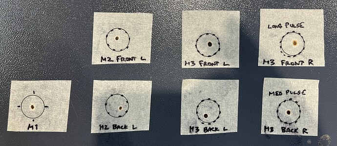
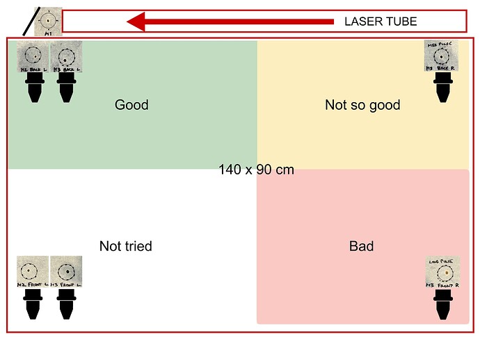
So here are the alignment burns.
One photo shows all the burns together and a second is the same photos laid out in place.
All pulses 130w at 15%
M1 and M2 burns were as short a pulse as I could manage, M3 needed a slightly longer pulse at Back R and a long-ish double pulse Front R. This is unsurprisingly the worst zone for cut quality.
I haven’t changed anything since posting yesterday, the workshop was too busy today.
These are so far the best settings I’ve managed. I’m sure that if I can get M2 firing in the centre at the back and the front, the other alignments will follow. You can see that M2 Back Left is low and to the right and M2 Front Left is high and to the left. If I centre M2 Back Left then M2 Front Left goes right to the top left edge of the frame and I played alignment tennis between these two yesterday without managing to improve it.
Where do I go from here?
Have to leveled you machine and work bed? That would cause that all.
@EtchTexas is relatively correct… these 3d cnc machine are on the space station, so I doubt level has anything to do with it…
What I believe he’s trying to ask is it square in all three dimensions… Gravity happens to be handy in many cases, such as helping to determine square… but gravity isn’t required for these to operate…
This means little, 15% for 1 second is substantially different then 15% for half a second… ![]()
I set my duration on the machine console, to around 10mS or less… might take more than one pulse, but it doesn’t depend on people timing…
It would be better if you can make your burns much lighter… you want most of the outside of it light brown, and the center not black… When it burns black all the visual information is missing… You’ll have to figure out what these settings are… you will find the more lightly you touch it the better the visual becomes as to what it’s doing.
M1, the photo, to me indicates your tube isn’t in TEM00 state… the dot should be perfectly round not oblong. It should be close enough to center. Except for the odd beam shape, we’ll let this pass.
M2 is not centered at ether end of travel. The rest of this is so far out of alignment, I’m surprised you get anything out of the end… ![]()
M2 back (closest to m1?) should be closer to center, dismissing that, at the front (most distant?) it’s not even close to the same place… you should be able to adjust this.
Use the same target for close and far burns, that way it’s easy to see how far off you are… if you get it with 0.5mm two targets won’t due… In this case they are so far apart, you only have to pencil mark them.
This is what I do when I get m2 in the ball park…
Mark it closest to m1… this is the point the beam need to coincide at both distances…
Roll it out to maximum distance… standing at m1, I mark it… if it doesn’t coincide, I adjust m1 and pulse again… moving it step by step to the close distance spot.
Since you have changed the mirror angle, the close spot may have moved, usually a small amount… so check it until you move one dot upon the other…
On my machine, I can barely reach the pulse button from where I can adjust m1. I you can’t reach it you’ll have to make the trip… don’t have any help doing this while you’re in the back of the machine…
This isn’t perfect, but it’s m2 both far and near. Gives you some idea of how far you are off… Compare the target at m1 in post 4 I posted.
Maybe this thought would help…
If you went to the 100 yard rifle range and put a sheet of paper a quarter inch from the muzzle, fired a round and it was 5" to the right… to fix that you aim more to the left and fire again… the hole near the muzzle won’t have moved hardly any, but the impact will. You have to move the distant dot → closest dot not vice versa…
What size are your mirrors? Remember that the beam is seeing full height mirror at m1, m2, but only the horizontal width at m3… I think it’s the Sin(45 deg), meaning you don’t have 20mm mirrors or whatever… so you’re alignment error is limited.
If your mirror is 20mm your limited direction will be the 20mm * sin(45) = 14.1mm This is the horizontal width of the mirror at 45 deg… beam is 6mm… 14mm - 6mm = 8mm… you will have ~4mm on each side for alignment error…
Some of these issues you have are that the beam isn’t correct for the mirrors somewhere at or after m2.
I suggest you should double check the m1 burn with a much lighter touch and determine if it’s round or not… it doesn’t appear round…
Generally this failure is the tube, but I’ve seen more than one fix being the lps replacement. Problem here is there isn’t a good way to determine which is which… Most of the time a tube is the fix…
Let us know…
Good luck
![]()
As always, I’m grateful to you guys for taking the time to help out.
Etch Texas - you make a good point. Before posting here we spent a long day trying to check levels and straightness of the chassis as something must have changed over the last few weeks to cause this problem. The machine sits on a good level concrete slab and we haven’t changed our daily routines but temperatures have risen since we installed the machine in the Spring and we wondered if these cheaper machines are affected by seasonal highs and lows. I can’t say for sure that this isn’t still a factor but after doing our best to check the rail system and machine geometry with a builders laser level, then raising and lowering individual feet, I couldn’t relate the misalignment to the small differences we were seeing when we did this.
Jack - I think today I need to regulate the pulse power to make the burn information more useful (I didn’t know this was possible) then work through your alignment suggestions. I can’t see the mirrors from the control panel but otherwise I can follow your instructions. I’ll come back with an update and new photos. Off to the workshop now, I’m starting earlier each day to make time to sort this, I think I’ll soon be in your time zone. Thanks again.
We had 113F deg temps here in the middle of Arizona (119F in the Phoenix area)… not a problem… much more rough on the chiller… Phoenix lows hasn’t dropped below the 90F deg mark in a month…
Doubt heat has anything to do with it…
Good luck
![]()
Change of plans. I started work extra early to get the last few panels of 5mm ply cut to meet a project deadline before getting back to the alignment. The cuts visibly deteriorated over the space 30 minutes, by the end of which I couldn’t get a single clean cut anywhere. Not a good situation but it could be worse - I ordered a second machine a few weeks ago because… well, life is unpredictable, and it arrived yesterday. I’ll spend the next few days getting the new one unpacked and running before I investigate further. However, machine number 1 is only 4 months old so it’s time to get the supplier involved. I think they’re a designated re-seller so I’m not expecting in-depth tech support but maybe I can agree replacement parts if I can diagnose the fault - what’s your hunch about the most likely issue ? And any thoughts on how a non-expert can start a diagnosis? I’m more grateful than ever that you guys are there, thank you again.
I’d suggest getting a good dot/photo of the output of the tube… if this is not in TEM00 state, you will never be able to align the machine…
Check that first with the vendor… I’d explain the problems you have during alignment and get their opinion of what the issue is…
4 months old, yes, I’d get the vendor involved…
Good luck
![]()
