I got my new machine uncrated and set up. It’ s my 3rd machine (the other machines malfunctioned). I’ve gotten the laser to where it’s hitting dead center in mirrors 2 and 3. I’ve watched a lot of videos and I had aligned previous lasers.
Now, when trying to do the vertical alignment, that’s where I’m running into issues. First of all, I took off the focus lens and placed some tape there as I’ve seen before on videos. I did this before on previous lasers and didn’t have an issue.
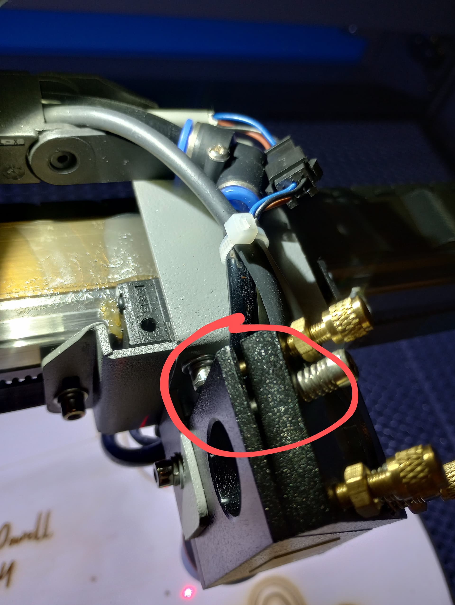
Then the tape showed that the beam wasn’t hitting in the center, so I went to adjust. The problem is that even though I’ve loosened the nuts (before I started) on the adjustment screws, the only way to get the beam to hit the middle of the tape is to tighten the screws, which causes the plate to pull away.
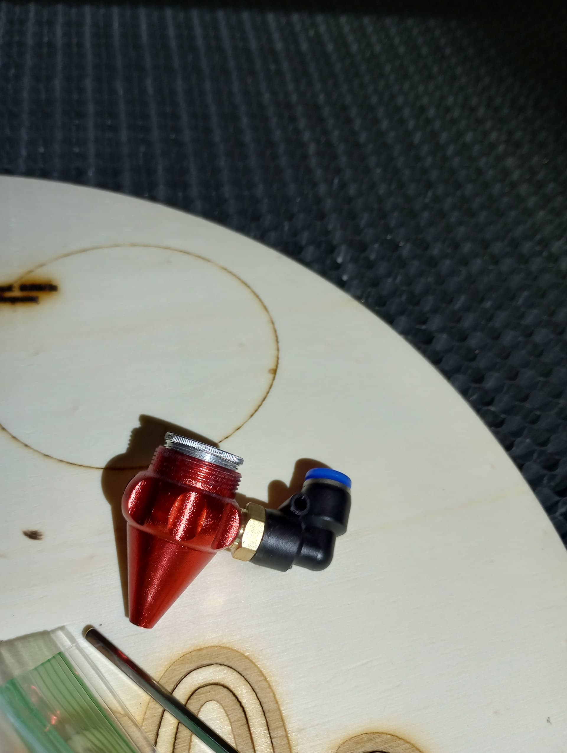
The mirror is secured to the plate. It needs to move to adjust the mirror.
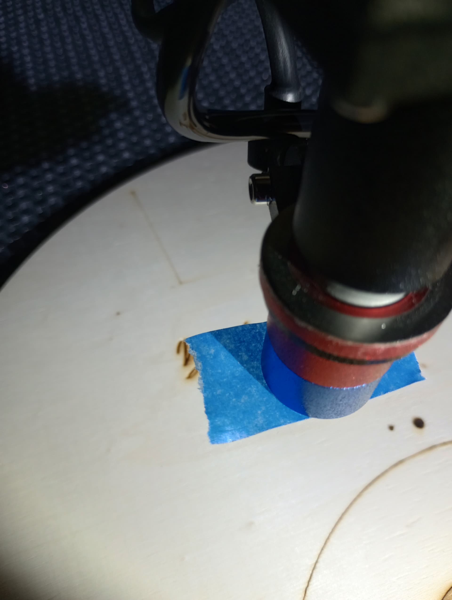
With the lens nozzle removed lower the tube all the way down and draw a circle around it on the tape. Pulse the laser and get the burn in the center of the circle.
Put the nozzle back on and press a piece of tape to the bottom of it. Press hard to imprint the circle into the tape. Pulse the laser to see if t’s coming out of the nozzle. Fine tune the adjustment to make it direct center.
Also if you removed the lens from the nozzle make sure it’s installed correctly. It’s easy to put it in upside down.
If that’s a light scorch, then the mirrors are severely misaligned and the beam is splashing off something inside the laser head.
Does the beam hit dead center at both ends of the X and Y axes? Or does it hit at only one end and is completely off the mirror aperture at the other?
Show the scorches at the entrance apertures to all three mirrors, with separate tape / targets for the four corners of the platform. That’ll be seven targets total: one for M1, two for M2, and four for M3.
That may seem excessive, but everything so far points toward an incorrect beam path, so let’s confirm or refute that right away.
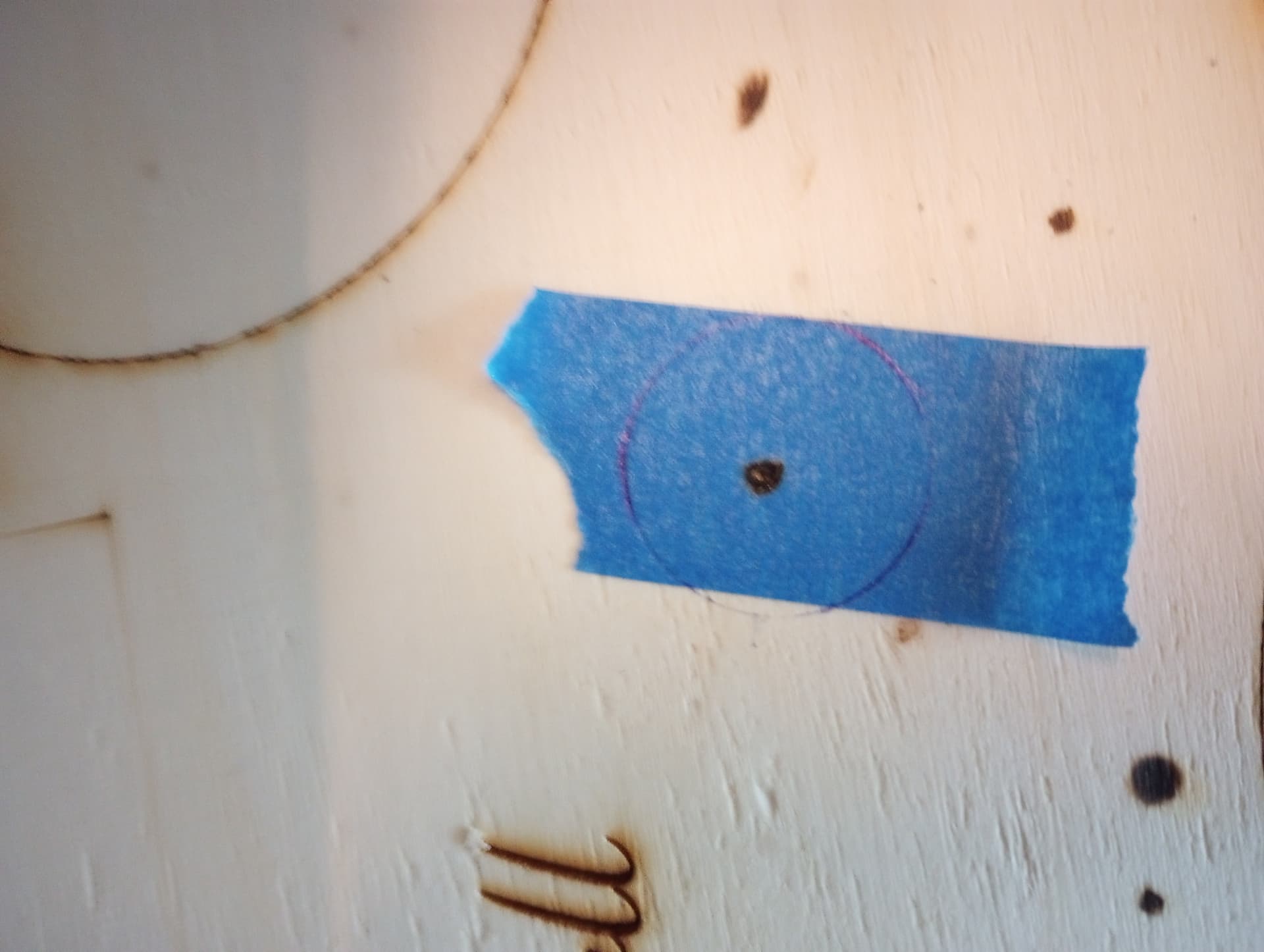
Hi, the ring on the blue tape around the central burn is just ink pen. The other stuff you can see on the wood (not the scorch mark on the blue tape) is from previous burns on previous machines.
As far as the request for tape examples for each mirror, I will get that to you tomorrow. Thank you for your help. Just so I know I’m doing what you are thinking, If you look the the picture below:
Mirror 1 is the first mirror at the laser tube. Beam should be centered on that mirror first.
Mirror 2 is the mirror that M1 reflects to. The beam should be centered with it near and far from M1.
Mirror 3 is on top of the laser head. The beam should be centered with it near and far form mirror 2.
The final step is to adjust mirror 3 to be center of the nozzle.
Remember that the marks at a mirror depend on the alignment of the upstream mirrors.
M1 is right at the laser tube, so the laser head position doesn’t matter. The scorch should already be centered, but you can also use that mark to verify the tube is operating properly.
M2 gets tested at A and B, because those are the limits of its travel. Make a scorch at A, then adjust M1 so the scorch at B overlaps it. That will take some iteration and the overlapped scorches may not be centered on M2, but should be within a few millimeters of center.
M3 gets tested first at A and C, adjusting M2 so the scorch at C overlaps the one at A. Then check at B and D, where ideally you’d find a single overlapping scorch. If the scorch at D is off, that’s known as the “fourth corner” problem and you adjust M1 (not M2) very very very slightly to fix it.
That aligns the beam path to be parallel to the axes, but the scorches may not be centered in the mirror apertures. If they’re within a few millimeters, that’s OK, but if not you must slide the mirror mounts to center the mirrors on the beam. This will inevitably require readjusting the mirror angles, but an iteration or two should get the beam both centered and parallel.
I then put tape on the bottom of the laser, it was centered. I put the nozzle back on, nothing. So I loosened all the adjustment screws on the laser head and suddenly I got the laser back.
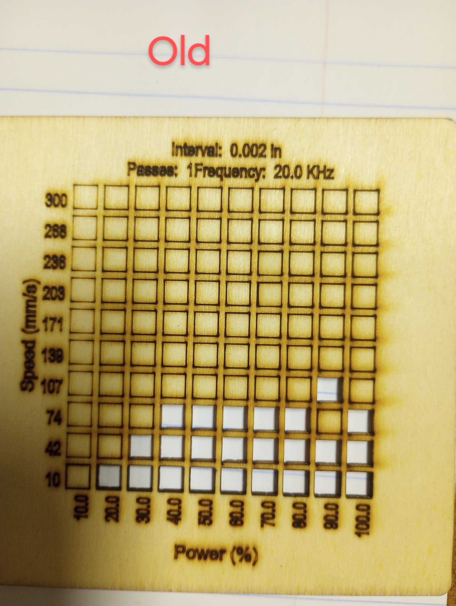
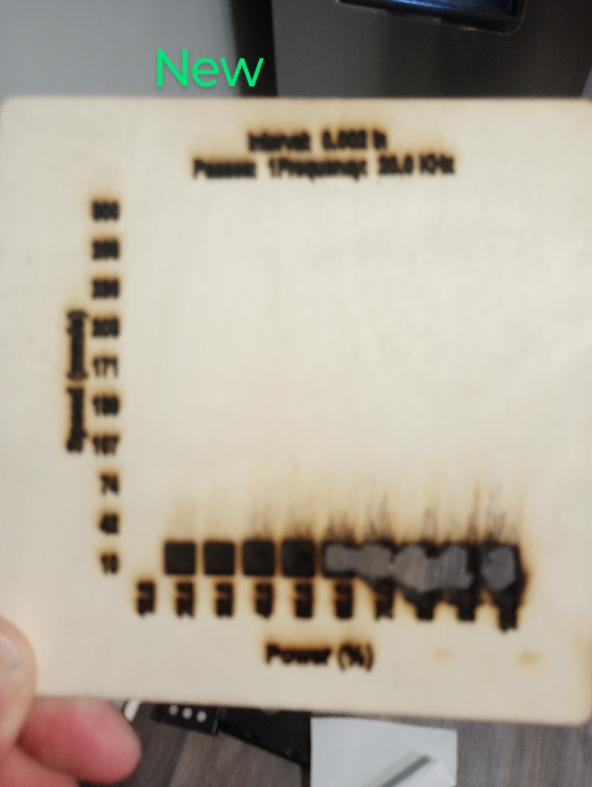
However, I ran a material test from lightburn. The first one is from the old machine. It’s not perfect, but you can read the words, etc.
Where do I need to start making adjustments so that this material test burns like the old machine (or better)? I’m obviously concerned that the new machine wouldn’t be able to do lettering in its current condition.
Which ones are those? The mirror adjustments or the ones that hold the entire head onto the X axis bearing follower?
If it’s now running with loose screws, don’t be surprised at backlash in the motions.
This needs fixing before you get good results.
The default settings for the Material Test are pretty much guaranteed to be wrong for any specific laser and, in particular, the text settings require tweaking because they’re not part of the speed / power range testing.
Turn the text layer settings down:
10% power (or the lowest power the tube will fire)
Hi, I meant mirror adjustments, not the screws holding the head on to the axis bearing follower. Also, I tightened the nuts back holding the adjustment screws. So nothing should be loose.
I would expect results like that at those speeds and power settings. Start at a higher speed for your engraving, maybe 100 instead of 10. Speeds around 10 are usually used for cutting.