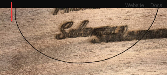
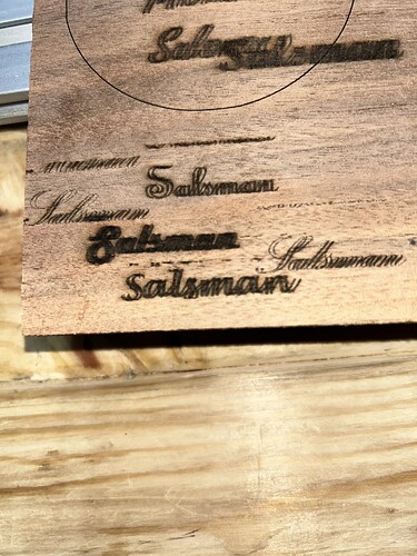
I am new to this and struggling with text. All the script text I choose seems to have a shadow or double burn. Jtech 14W with air assist on Millright CNC. Any help appreciated!
Filling in the Scanning Offset Adjustment table with measured offsets will fix that:
Using simple squares with the Line Interval set to 1 mm will simplify the measurements.
Thank you I will try that this afternoon.
99.9% sure this is a X axis belt slack issue
Try this, uncheck Bi Directional engraving
IF the machine stops doing ghosting then is your X axis slack, or belts that are not tight enough
My MillRight has rack and pinion not belts.
If that were the case, we’d also hear about the ends of vector cut circles (as in the one shown in the picture) not lining up. ![]()
As a rule of thumb, nobody starts out knowing about the scanning offset problem, so (in the absence of other evidence) fixing the offset generally resolves the “shadow or double burn” issue.
Fair point, from my experience, though, this issue is caused by something else
You can mask it or fix it
I guess both approaches reach the same end goal.
With both “tool sets” is dealers choice on what to do ![]()
Aditionally if you notice, there is in fact an issue on the X curves.

Definitely better to fix the mechanical problems, although nobody believes they exist.
Good catch!
However, that error is much smaller than the offset, so doing the mechanical tuneup dance will be next.
2mm worth, usually a full belt tooth ![]()
Trying to work on this a little but not exactly sure what I am looking for.
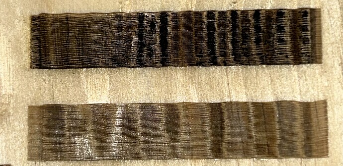
Top box at 100mm/s
Bottom box at 200mm/s
I did go play with the scan offset entry for 100 and 200 and set the line shift for .6mm for 100mm/s and .7mm for 200mm/s just to see what I was doing to the output and it did make a major improvement in the ghosting issue.
Not sure what to measure on the two test box lines.
Again thanks for your help this is very new to me!
Diode lasers tend to use mm/min, rather than mm/s, so you may want to switch that in Edit → Settings to avoid confusion speeds from other folks.
In any event, 100 mm/s = 6000 mm/min, which is moving at a pretty good clip already. To make the Scanning Offset Adjustment table useful, run the test with squares (no need for a long rectangle) at speeds from 1000 mm/min to as fast as it can go (*) in increments of 1000 mm/min to get a broad range of speeds.
This was a target with 1 mm squares on acrylic, run at speeds from 100 to 500 mm/s on my CO₂ laser:
Notice how the offset between successive lines increases with increasing speed, which is why you must test a wide range.
Set the line interval to 0.5 mm so each scan line is distinct, which will make it easier to see and measure the offset between successive lines, then put half that distance in the table.
A measuring magnifier makes it easier to, well, measure such small distances.
When you get it right, the difference is obvious:
Keep on tweaking! ![]() :
:
(*) As limited by GRBL parameters $110 and $111.
Thank you for this detailed explanation. I found how to change to mm/min and will run the test tomorrow to try and get it tweaked in further.
As @gilaraujo points out, there is likely some mechanical slack involved and adjusting / tightening / removing those problems will definitely help.
You’ll find removing backlash from the X axis will affect the offset adjustments you just made, so expect to re-measure and re-adjust as you improve the machine’s condition.
There is something peculiar on this image
you notice the wavyness?
if you hold the laser head with your hand, and apply rotation
Up and down, left right, back and forward
Do you feel and slack between wheels and the frame
I would say either you have a not so good wheel or your X axis has some slack also on the wheels vs frame This should be adjustable by a set of eccentric wheels
if you can take a couple pictures of the machine i would be able to do some doodles on it
This topic was automatically closed 30 days after the last reply. New replies are no longer allowed.


