Anybody using the BOSS with Mach4 upgrade?

I currently have a Boss LS-3655 with the normal “hybrid servo” but have another with the Mach4 upgrade on order to replace it. I’m curious is anything has any first hand experience raster engraving with the Mach4 upgrade and can share their experience. Boss’s marketing shows it rastering at speeds of 2,000-2,300mm/s but with the standard Hybrid servo drive I’m struggling to get good quality above 500mm/s even though the hybrid servo is supposedly good for up to 1,500mm/s.

Anyone have first hand experience rastering much faster than 500mm/s with the Mach4? I’m going to be engraving alot of anodized and coated metals, which show defects and require good quality. I’m assuming wood is a bit more forgiving, but haven’t done much wood work other than cutting out jigs.

Is this a dc or rf laser?

Most glass tubes, dc excited, where control is limited by the response time of the laser power supply (lps).

Mine will run 1650mm/s, but I can’t engrave anything at these speeds… I keep it in the 200mm/s to 300mm/s range most of the time.

:smile_cat:

Thanks for the response. That’s more or less what I’m experiencing with my current laser. I find that I can engrave at 250-300mm/s with really nice (near perfect) quality. bumping up to 500m/s has a very slight decrease in quality, but still very good. But going to 600mm/s+ starts to have noticeably more and more decrease in quality as speed increases.

I’ve heard it’s limited to the response of the laser tube or power supply which makes sense. I have seen several videos of the Mach4 upgraded machine running at 2,000mm/s while rastering a fairly large image (looked like maybe 18’x18" or so) and was able to complete it in 15m:37s vs 1h:13m:44s with the standard machine running at 400mm/s. Here’s a link if you’re interested in seeing it, directly from Boss’s youtube channel. I understand marketing often cherry picks the perfect files to run at the perfect speeds that has the biggest most dramatic effect but the evidence is there. I’m not sure if they have some special lps that has a faster response time or what. Looking closely at the final result, you can see the image quality isn’t quite as good so I’m sure they are pushing the speed a bit for the video, but even if I could get half of that speed I’d be ecstatic. I guess I’ll get some first hand experience hopefully soon.

I understand the overscan issue with going at such high speeds, but the video does account for that as well with a real run of the laser. They do claim higher accuracy and acceleration along with the increased speed, so it seems they are accounting for some of the overscan problems with higher acceleration values. They make no claims as to the levels though, so I’ll have to wait till i get mine in to see what those settings are.

Most of what I’ll be engraving are 48" x 24" and the engravable area on my laser is 55" x 36" so I should have some room for the overscan, and can dial back speeds if needed to optimize for my size products. Being such large items, increase speeds start to make up for the overscan time vs a small keychain sized object for instance.

I had a brief moment of concern before I realized Mach4 is what Boss calls their servo upgrade, not the controller they are using (the other Mach 4 https://www.machsupport.com/software/mach4/)

Agreeing with Jack here, using a glass laser tube with servo drive is almost a waste of money. You will see some improvements, but you’ll certainly want a RF tube to make the best use of the hardware. You end up just changing your bottleneck from the motors to the LPS, that’s all.

2 Likes

Thanks for the input. I kept coming across the Mach4 software you referenced when trying to google it as well.

That’s too bad about the limitations on the glass tubes. Unfortunately they only offer the RF laser on their much larger machine and is quite a hefty price increase which quadruples the cost of the machine. I wonder if there are aftermarket RF tubes that could be swapped out if I found it necessary, or if that’s a much more involved and not worth it thing to do.

It seems some other brands offer an RF laser but not on the size machine I have. I’m certainly not sold on Boss after the massive headaches they’ve caused me so far (that’s a whole can of worms but I’m not trying to go bashing them too much so I’ll just leave it at that). If the Mach4 one doesn’t perform much different than the one I have now I’ll look elsewhere for my next lasers. I was hoping to have all of the same kind of laser for ease of maintenance, programing, and spare parts inventory but I want to make sure I have the right laser before getting more of them. While speed is important for me for throughput, quality is more important and I don’t want to sacrifice quality for speed. I’d rather buy more machines to increase production than to make bad quality products.

Let me pick some numbers here and you can see what’s happening… first the video…

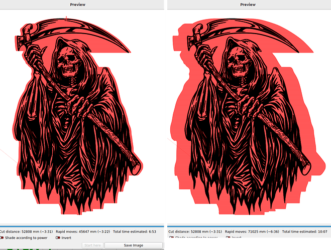
Anytime the head is not over the work, it’s not doing anything, so this slow down, change direction and speed up is wasted machine time… I use this as an example, but you can use the same scheme to check your artwork… I think you may have to open the machine settings under edit to read the controller information, it might have it…

This is a 50mmX100mm rectangle. This is the preview, one of the greatest tools in Lightburn that few actually use to it’s potential. It’s saved me tons of materials and helped me keep some of my hair.

The acceleration is set down to 8000mm/s^2, around a lot of these Chinese machines. I’m sure it’s is much higher… Mine gantry and head has been lightened and my acceleration is around 45,000mm/s^2. Red is overscan and the less of it is the key to a fast job…

There is a very light green box, this is actually the defined work area, so you would over scan out of your work area doing this, if all of this is configured correctly. Notice I spend more time at twice speed than at regular speed.

This is mine with an acceleration value of 40,000mm/s on an image… speeds are the same, only acceleration has changed. On the right is the 6,000mm/s preview. Note the elapsed time and size of overscan.

I think making use of what you can control seems to work best for me.


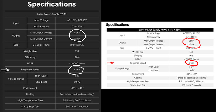
The second item is the lps response time.

Most of these lps are tested to reach 90% of the placard voltage in <=1mS (1/1000S or 1kHz). This means that it will take you 1mS for the tube to lase. 1mS is 1000 times a second or 1kHz frequency wise.


Use this worst case 1mS response time as an example…

If you can run 1000mm/s, which you can, the best resolution you could get within the response time is 25.4 dpi. You can only turn it on quick enough every mm.

If you half the time to 500mm/s that doubles it to 50.8 dpi, at 250mm/s 101.6 dpi…

This is, in the real world nothing we usually measure we just assume it works… but the numbers makes one question how this is actually working.

I said this is worst case… a response time of 1mS, it can be lower and still pass. Without measuring a few of these for comparison we don’t know how many are <1mS…

You can hedge the odds, but putting in an lps that has a higher voltage and consequently should have a faster response to a lower voltage.

Right above the response speed is mean time before failure (MTBF) or it’s expected lifetime…

Make sense?

I agree the slower one looks better… :grimacing:

:smile_cat:

I think that all makes sense. Certainly the overscan time, which is highly apparent on a small engraved work piece.

The response time of the laser power supply makes sense as well. If it can only respond (turn on or off) at a 1kHz rate, than I’m only going to be able to switch the laser on/off every 1mm if traveling at 1,000mm/s. With that limitation, the only way to get finer resolution is to slow down the head speed, or to increase the LPS frequency.

Briefly looking, it seems “<1ms” is a common rating for response time. However, there is a huge difference between 0.5ms and 0.9ms response time which would both meet the stated spec.

You mentioned that going with a higher voltage LPS could increase the response time…did I read that correctly? The LPS’s aren’t terribly expensive and could be very much worth swapping out if that would help bump up the speeds with increased response time. Would that damage the CO2 tube going up in voltage though?

The higher voltage lps will get to it’s placard voltage sooner, therefore a lower voltage tube would respond faster as it has to surpass the other lps output voltage.

Is this what you’re thinking?

:smile_cat:

It’s a dc supply, what frequency?

If you mean pwm period, that won’t change anything either. The IN control of the LPS is actually both digital and analog. So there ends up being no change in controls to the LPS is you run an analog or digital signal to it.

The only option I know of is to upgrade the lps… and I’m only going by the devices specifications.


If you really want to do this, I’d suggest you come up with a way to measure it. That’s the only way to truly know what’s going on.

I don’t know what happens when you drive one of these past it’s bandwidth, but we seem to do it a lot.

Good luck

:smile_cat:

And even more between whatever that means and the frequency response at the IN terminal. :frowning_face:

I measured some of that a while ago

Start with a sine-wave test pattern:

That’s contrived so each bar is 1 mm wide with 0.1 mm pixels at 254 DPI. Engraving it in Grayscale mode lets each pixel value directly set the output power and scanning the pattern at different speeds changes the frequency of the sine wave signal going into the HV power supply at 1 mm/s = 1 Hz.

Scanning at 50 mm/s shows the current does reach full scale, although it’s obviously not linear:

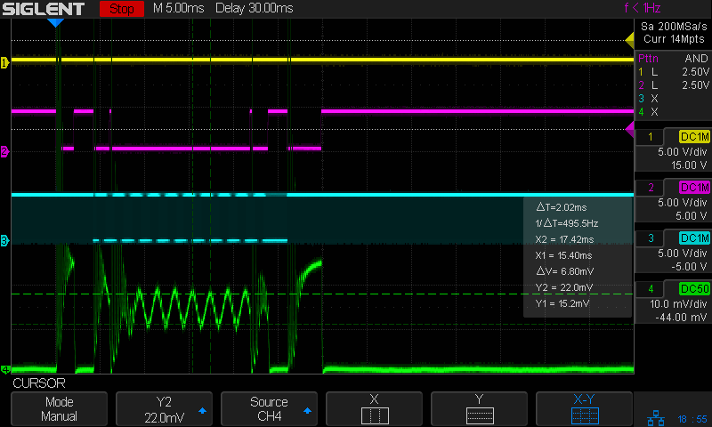
The traces:

  • 1 X axis DIR, low = left-to-right (yellow)
  • 2 L-ON laser enable, low active (magenta)
  • 3 PWM digital signal (cyan)
  • 4 tube current – 10 mA/div (green)

Speeding up to 200 mm/s = 200 Hz shows that the current no longer reaches the extremes, so the tube never fully turns on nor shuts off:

And at 500 mm/s = 500 Hz, there’s not much signal left:

So the “3 dB bandwidth” into the IN terminal is around 200 Hz, more or less, kinda-sorta, which implies a step response on the order of 2 ms to PWM (or analog) changes.

The response to the digital enable signal on the L terminal is more complicated: the turn-on current oscillates for a few milliseconds and the turn-off is nearly instant.

AFAICT, the controller turns the L-ON signal off when the power output set by the PWM output should be zero, which means that oscillation will blur the off-to-on transition: at 500 mm/s, a 2 ms oscillation will be 1 mm wide. This means the faster you try to scan binary dithered images, the worse each pixel will look.

So, although a higher voltage power supply might improve the response, I’m reasonably sure you’d never notice the difference.

I’d have to agree…


Love your 1Hz pwm… never tried it that low…

:smile_cat: