Did you open the box and have a part # for the opto?
@Hank from another thread someone posted it was Toshiba TLP785, but it comes in two versions thru hole and surface. I really wanted to only take controller out one time so I was hoping to get confirmation from someone who has done it.
If you are registered on RDWORKS forum someone uploaded some great pictures but you have to be registered and do an intro post to see them, here is link:
https://rdworkslab.com/viewtopic.php?f=123&t=4798&p=29966#p29966
Ahh yes, I remember that thread from last year. I’m surprised I refrained from comment in it, I certainly spent lots of time analyzing the photos and I did download the datasheet for those optocouplers.
Here’s what I think I know about that controller board.
First of all, there are no optocouplers on the OUTPUTs of that device.
The outputs on CN1, which are Out2, Out1, Status, Wind are all transistor driven outputs. Probably some kind of n-channel MOSFET.
There are 4 in a row in the upper left corner of the photo that Chad has circled and commented that he thinks it’s damaged. If you have a blown OUTPUT then one of those likely needs replacing.
There are also 4 diodes above them which are reverse emf protection for those transistors.
The INPUTS, which are on CN2, CN3, CN4, are all optically coupled and there are 12 optocouplers on the right side of the board for those 12 INPUTS.
If you’ve got misbehaving outputs, those optocouplers are not your problem. Optos are on the inputs only.
@Hank so the Ruida Owners Manual says the following after the CN1 output block description " All outputs are isolated through the optocoupler, and 500mA current for each,
OC gate output, each can directly drive the 6V/24V relay"
There are 16 opto’s on board, maybe the other 4 go to CN1??? Im probably gonna have to ohm this out. Im on mousser now, the Opto’s are only 50 cents and Im sure that 1P transistor is cheap too, I may just order a few of each since its the 8 dollar shipping that gets you. I miss Radio Shack  I do see they are thru hole version now that I looked at pic better.
Any guess on Diode Size?
Open collector circuits generally have a pull up resistor to the VCC. When the output is energized it grounds the signal, when it is not, the signal is pulled up to the supply voltage by the resistor. Try using a 10K resistor from OUT1 to 24v and see if that rectifies the issue. If there is a pull-up resistor on the board, look for it and perhaps there is a broken solder joint or a burned resistor. Just guessing as I have no idea what board you are talking about.
Generally Open Collector ‘OC’ outputs for devices depend on the connection to supply the voltage.
If the device being signaled is not powered up then the OC has no reason to function anyway. Pull ups draw current, produce heat, take up board space and cost money in development and parts.
Without a schematic you don’t really know what they were thinking. Sometimes with a schematic you don’t know what they were thinking either.
I also saw diagrams of the outputs going through optical isolators and it makes sense because the board logic probably does not run at 24 volts. Good way to isolate the logic from users wiring
Of the hardware I’ve worked on most isolators are LED/Photo diode/transistor, so they generally switch a power transistor and in this day and age more likely a power mosfet of some kind. Add to that they generally don’t allow much more than 50 ma, kind of eliminates them from driving 300ma or more.
Output from the coupler driving the fet, no output from fet → replace fet? Schematic (road map) would sure help. You could probably check this with a DVM.
I would ensure that there are protection diodes either on the board or within the mosfet to handle connecting coil based air valves and such.
I read the basic info on the 6445 on the Ruida website, it stated a max current sink of 300 ma. Conflicts which shouldn’t surprise me
Wish I had a nickel for every time I was only going to do this once
Keep up updated, we are all on the edge of the seat
Take care
Thanks everyone. I will definitely update, I hate reading through a thread and you get to the end and no one posts final solution.
Right now I am in a holding pattern waiting on what Orion Motor is going to do. Customer service was great first couple days of debugging issue but this morning I get a an email from a new guy who opened last message and didnt bother reading history asking me to take pictures and videos of the same things I already sent. I was previously offered 100 bucks to go away, but honestly, I just wish they would send a new controller and Ill send this one back, or refund 238 bucks and Ill get a new one on ALIexpress. I asked for that today. Its a brand new machine. Also, on Facebook groups today someone else seems to have a new machine with no output on WIND despite enabling the settings correctly on the layers. Not totally issolated issue it seems and with all the electronic component shortages going on maybe some bad batches of parts are in the supply chain…
I can get the optos on Mouser and fix myself if all else fails, just hate to randomly replace octocoupler when it could be the FPGA or something not even generating the signal.
In my setup I do not attempt to drive anything except a 24V relay and Im only switching a 24V signal. This relay drives my 24v/110 relay to do the heavier work. So I’m pretty issolated from the control board and causing damage.
While I don’t know how to fix your issue I thought I could at least explain what an opto coupler (also known as an opto isolator) is for you. On the side that connects to the control chip it is a IR (infra red) diode and on the other side it’s an IR receiver then this is potted in a plastic case. The computer turns on and off the diode and that tells the receiver it got a signal all while being fully electrically isolated from the main circuit, this helps prevent feedback from electrical noise as well as preventing damage to the mail components should a voltage spike hit the output, it will fry the opt-isolator but they are cheap and easy to replace (if you know how to unsolder and solder).
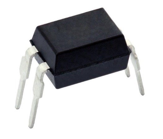
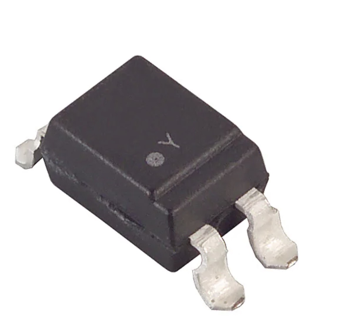
Here is a common one, $0.47ea.
Through hole? Ewww… how 80’s. 
I got a $240 refund to purchase a new controller, which is what they go for on aliexpress and all I asked for. I bought the parts needed to fix first and will try that first. I’m traveling like crazy now so probably a month until I have free time to get to it. I have a little in circuit component tester, I’m going to see if that will excite diode and measure diff in output while doing so. I’d like to verify the bad components before removing if possible
I’ve opened up a Ruida 6442 before. It’s a surface mount 4 legged guy on the bottom of the board so it shouldn’t be too bad to replace. Compared to trying to get a smaller smt component out from between a bunch of plastic connectors you’re trying not to melt, it’s super easy.
Hmm, photos on RDworks forum are thru holes
Hmmm… it has been a bit, my memory might be rusty. Open it up and take pics of yours anyways. Either way shouldn’t be too bad to do the job.
IMHO, you’re wasting your time… The output in the manual does show these as the output, but it’s a commie plot…lol… These isolators are usually limited to around 20ma. That would not support even the minimum current in one of the Ruida documents of 300ma, let alone 500ma stated elsewhere. Check the $0.47, I highly doubt it supports over 20 ma.
These are to protect the controllers internals. If you look at how these are generally hooked up, they run the 24 power supply line to them. What kind of isolation is really needed? Just isolate the 24v from the 5 v digital circuitry.
Don’t get fixated on what appears an obvious solution. It should be easy to check if you can power the board up or just remove the cover where it sits. If the ‘gate’ of the driver is switching, and the driver doesn’t switch…
If anything is history or “lost it’s smoke”, it’s the power mos fets that do the actual switching.
But keep us posted
Been traveling like crazy, hope to make this mod this week.
This topic was automatically closed 30 days after the last reply. New replies are no longer allowed.