I used search function and found a couple posts where people had strange voltages on CN1 outputs. Mine behaves similar but those threads are closed and no one updated the final solution.
Basically my STATUS just floats, it is never driven low during job start, and my OUT1 seems like it attempts to switch but only goes from GND to float, it does not pull up to 24V.
My first goal was to use STATUS to energize a relay that has 24V on one side of coil and STATUS on other. The NO switch would close and connect 24V. This 24V signal triggers a delay relay. Basically I am just reversing polarity of the negative STATUS control signal. Anyway, this clearly wont work since I see no activity from STATUS.
Now, I’m curious if OUT1 is operating correctly. It seems like it does indeed hold GND. But when laser is active and it releases GND should it just float or should it be driven(pulled up) to 24V. My goal initially was to use this as a positive trigger on the coil. So this will be the 24V to coil with other side of coil grounded. But since my system is not truly pulling it up this doesnt work either.
It seemed other users have been down this path and there was talk of damaged boards and needing to replace transistors or optocouplers but no followup to say what they did or if they resolved, so just reopening a similar thread. Thanks to whomever can help. Circuit card modification is easy to me I just wanna know if its what needs to be done
Thank you @Hank , it looks as if my STATUS is probably damaged and my OUT1 is working.
So then, my work around, at least all I am thinking of, would be: Use OUT1 to energize relay the entire time the machine is idle and when a job starts the relay will be deenergized and allow the NC switch to turn on exhaust fans.
I don’t like idea of energized relay the entire time machine is idle on, much rather have it only during job run time.
Don’t write the controller off so quick, I’d venture to guess if it’s wired right, it’s not enabled in the Ruida configuration somehow. I had laser 2 enabled in the configuration that stopped ‘status’ from working as expected.
In the Ruida manual I have advises about ‘Out1’ that it is “General output, with function reserved.” So in simple terms nobody really knows what it does and Ruida isn’t going to tell you. I’d stay away from that type of guessing game, unless you have some other knowledge you’re not telling us about
There is a major misunderstanding of the Ruida controllers interfaces. It has inputs and outputs, like all controllers, what you need to keep in mind is
1.) outputs are actually ‘output sink’ where the controller ‘completes’ the circuit to ground. This requires the + side of the controlled device (such as a solenoid) be connected to 24v supply line. When the output is active it completes the path to ground or ‘sinks’ current.
2.) inputs are ‘watched’ by the controller. The controller uses a ‘pull up’ resistor to ensure the line remains in a high state when unconnected or ‘inactive’. No 24v needed here. On my Ruida, it reads about 22.something volts open. Any device that wants to activate that input, only has to pull it to ground (or logic low).
This means it’s easy to put a mechanical switch to ground for a limit switch. Since it’s a ‘wired or’ you can have a limit at each end of all axes. I have 5 on my CNC3018, I can set any corner to ‘home’. It can’t tell which end of the axis, but you tell it the ‘seek’ direction for homing in the configuration.
I did see on the 6445 partial data that it can sink 300 ma. My suspicions are that the ‘sink’ capabilities of all outputs together are 300 ma.
Hope that clears up inputs and outputs, hope it’s a simple configurations issue.
I have my ‘Status’ turn on the air pump and fan via a ssr. ‘Wind’ bypasses the low pressure valve so I can select low for engraving (no air assist) and high (air assist) for cutting.
Thanks @jkwilborn . I wanted to use system same as you. Still waiting to upgrade air assist but hopefully in a few months
As far as I have researched, STATUS is automatic and there is no software/firmware enabling required. If someone knows differently I would love to know how and really wish it was as simple as mine not being activated. Im not looking forward to replacing an optocoupler, I am an electrical engineer, but I am no technician and I do not solder on a regular basis.
I do successfully have OUT1 running the exhaust now. OUT1 is complete opposite of STATUS. Only downfall (which I really dont like) is at machine initial turn on the relay is not activated until the controller comes on line and drives OUT1 low, this takes a few seconds. Without the relay energized the NC is 24V and driving my delay relay so my exhaust fan and anything else controlled by OUT1 runs at power up. This is a good 30 seconds because of the delay relay.
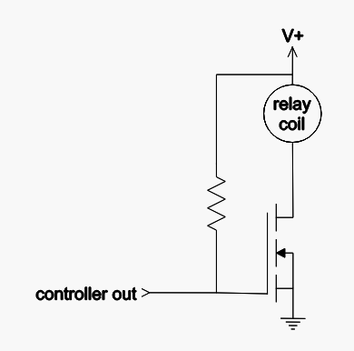
You could use an NPN bipolar or N-channel MOSFET to invert the output.
When the controller output is inactive (floating) the resistor pulls the gate or base high and the relay is energized. When the output is active (pulled low) the transistor and relay are shut off.
@Hank good idea, I guess my concern would be how sensitive are these Optocouplers to damage and will 24V damage it. My STATUS was either DOA or damaged easily. I have zero experience with Optocouplers, never even knew about them until recently. Their job is to protect but one would think they shouldnt damage easily.
I am measureing with a digital multimeter, GND of the CN1 terminal post to STATUS of the CN1 terminal post. Absolutely nothing connected to CN1, just measuring voltage, hitting job start and watching meter. Nothing happens on STATUS, it just floats around 12V.
Even though nothing happens with nothing connected to CN1 I still wired it up as follows to try to see: I wired the negative of the relay coil to STATUS. Positive of coil to 24V power supply. I then strapped same 24V to PIN 12 which is normally closed to PIN 4. PIN 4 is a no connect. PIN 8 is the energized switch pin which will send the 24V to the delay relay. The setup works as I can take a GND signal and apply to negative of coil and relay energizes, It then correctly sends 24V signal to delay relay which energizes and turns on exhaust.
Also, with relay connected, STATUS just floats up to 24V if I measure with multimeter, it never even attempts to drive low.
Since status doesnt work I am doing complete opposite of above. OUT1 is negative of relay. 24V supply to positive. Normally Open is 24V and the energized signal is no connect. So this sends 24V to delay relay when OUT1 is floating, which is during laser run time and initial machine power up. It works, I just have annoying machine start up starting fans.
Have you done this since the configuration change with laser 2?
May not get desired results with a DVM. The input impedance is too high for the devices to switch properly. The relay load should work fine. I would expect the ‘floating’ 24v when ‘status’ is not enabled. You are just reading the supply voltage through the coil.
Really only interested in the coil connection.
I assume you are measuring this on the coil? If so I’d suggest you do it at the screw terminals of the ‘status’ port. I’ve seen a number of these and they are pretty tough animals but…
If you measure with your DVM between ground and ‘status’ it should show the 24v. Stay off the wires and hit the screws or metal brackets. It’s a long shot, but they do fail to connect sometimes.
I’m running out of options… I have this nagging that it’s configuration. I’ll keep looking. Need to do dinner…
My years with this type of equipment and computers in general, when the manufacturer tells you it’s reserved, heed their warning. Generally leads to grief if you. OUT1 just ‘seems’ to be doing what you want. What if it has a programmed function you’re not aware of and changes state in the middle of a job? Probably not a good idea.
Take care, make sure you retest after the laser 2 was disabled.
@jkwilborn yes, I was so hopeful too, but it was the same scenario. I may go toggle them again through Rdworks and see if anything changes but Im not hopeful as it reads back correctly through software. I even cycled power to make sure it didnt need a power cycle.
RDWorks has some sub menus, I’ve head that allow other options. There is also some version that allows even more. I don’t have a windows machine, so I haven’t done anything with RDWorks.
Dug up my usb stick that came with the machine and loaded RDWorks on my wifes machine. Couldn’t find much of anything. Sounds like the hardware is wired right… Did find the password is “RD8888” if you need it. Make sure you save a copy if you modify it.
Ive clicked on everything I see in RDWorks and didnt see anything that stood out. For kicks I tried the LAMP enables also but they didnt do anything. I tried enabling dual laser and back to single laser also, no luck.
I measured at multiple spots with same results, at terminal post of CN1, at relay screw. I even tried a new relay and new relay holder, but same measurments resulted. I am using a very nice Fluke 45 and it measures the switching of OUT1.
I havent messed with WIND/Air Assist settings yet. Those shouldnt matter, but itll be the last thing I can think of.
Also, my version is 8.0.67. I saw someone post from March this is the latest as of March.
It’s a nice meter. Many open collector sinks will not operate with a high impedance meter. As I updated my last post, I tried it with RDWorks, also same dismal results.
Putting the relay to 24v then grounding the other end should cause it to ‘pick’.
Where did you get the idea to use OUT1?
Well I’ve kind of run out of ideas. I’ll think about…
Just searching forums I read OUT1 is at least currently a mirror image of STATUS. Versus OUT2 which is a fail mode signal and only drives when something fails, like no water flow. I will have to be careful if I update software/firmware in future in case rdworks changes operation.
Im probably going to buy the Toshiba Optocoupler and replace and see what happens. If that blew it maybe did what it was supposed to do and rest of circuit is okay. There’s a transistor on that circuit also and it doesn’t look like I’ll be able to get a part number off it so hopefully just optocoupler. I’m also hoping it’s surface mount, online pics I can’t tell and I haven’t taken mine apart yet. Machine is new so I’m waiting to see what orion motor tech says.
I’d definitely try and get the factory or company to fix it. I had mine less than a month and started hacking on it. Have had good luck so far, hope you do too.