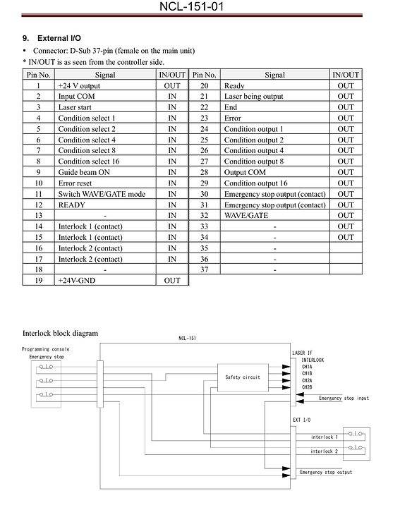
Hello everyone, I would like ask whether is it possible to use Arduino to control External I/O of laser of controller. As seen in the data sheet. However, it is mentioned of 24VDC input which I am not sure how overcome the problem being the Arduino only support lower voltage. Is there a solution for this?
So that’s one problem, another being that is there any safety I have look at since high powered laser and I am quite new to this field of External I/O programming. I have the HMI controller, However, I have stepper motor to control for my project as I am still a student. Any guidance in this issue will be much appreciated
You were not very clear about what you want to do, in the end.
You can’t control what the fiber controllers outputs, but you can use these signals for other purposes.
Most of these don’t really give you much information on how they work. This has always been an issue.
The 24V issue, is likely not really an issue, most of the electronics operate with 3.3V or 5V. The only way to tell is get in there with a scope or voltmeter. I don’t remember seeing anything about voltages on the JCZ board I have, but I may have just not noticed it.
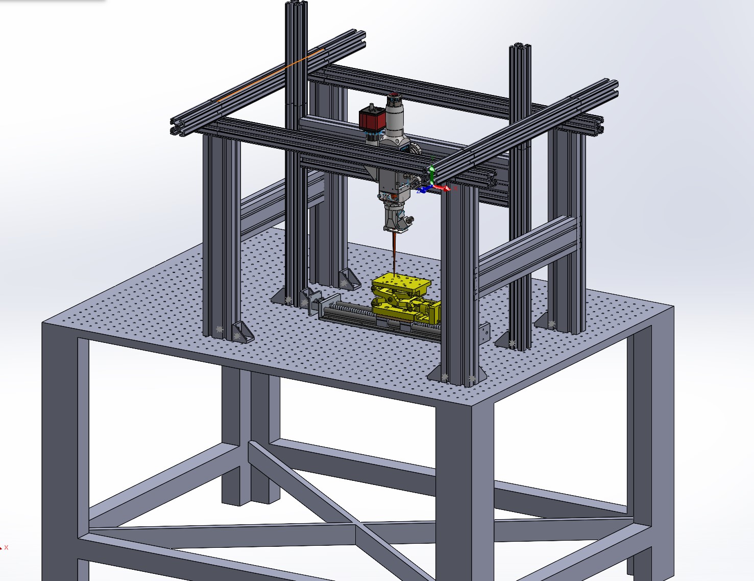
Are you cutting metal with this? Is it a gantry machine?
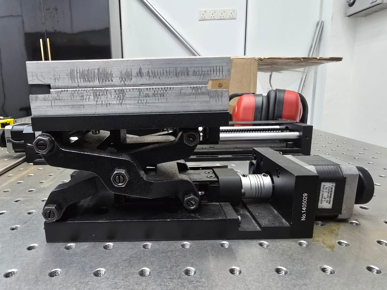
I am conducting a project called Wire Laser additive Manufacturing. I would inquire whether is it possible to program Arduino to be a control system, something similar as CNC control panel. I am integrating MIG wire feeder, Shielding gas tank, Laser Power system, and XZ linear guide motion. I am planning to use Arduino for XZ linear control motion.
Regarding your statement there: I can only take output signals only to arduino but I can’t give input from Arduino to the controller. Am I correct here?
Main Idea: Laser used to melt the Wire to create a single layer line for the time being
You certainly can use an arduino for control - but I would probably recommend something a little more robust for data processing - either linuxCNC or a duet
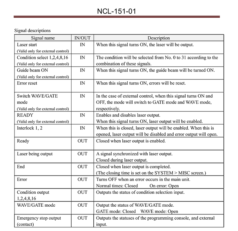
I don’t know what each of these signals do or how to tell the laser source when to lase, power, q-pulse and frequency.
The pinout you posted shows many connection and typical of the Chinese it’s next to impossible to figure out what some of them mean. They are written in Chinese and somebody, with little technical knowledge translates them to English.
You can probably make use of some of these if you figure out what they do. As far as controlling all the feeds you need, might be a bit much for the Arduino. An ESP32 of some type might be better as it’s clock is ~230mHz and the Arduino is ~16mHz.
As I stated, if you can get information from the manufacturer or figure out how the output pins and input pins work, you might stand a chance..
Current project I will be controlling IO ports Gin 14, 15 with the 3 and 4 pins off an Arduino Uno using a couple opto coupled solid state relays. (That’s the plan anyway) Think I can send a signal back to the Uno from Gout 4 or 5, which ever one is not in use (Ready Light). Plan is to run an XY table, already running the Z axis stepper with a Uno and UGS
Yeah I agree. No matter how many times I read the manual, I still don’t understand the whole system. On Arduino part, I will look into it.
I will try asking the manufacturers again. Before this, they mention just refer manual😅
I’m real basic in my understanding of these systems. Using IDE to flash the UNO, in the config I enable the pin 4 as a second cooling output so M7 M8 will turn on the relays, M9 off , all signals HI. The solid state opto coupled relays have a VCC/ JVCC jumper so I can run the coils off an independent power supply and really isolate the UNO. There are 2 inputs on the BJJCZ board 14 and 15 (Pins 1 and 9?) that can turn on or off the laser (Think foot switch), and there are two that can send a signal back (Think Ready Light). I’ll opto couple those also and power the coils off the internal 5VCC rather then the BJJCZ. All this is “The Plan”, have no idea how much success I’ll have. May be buying another board if I smoke test this one, should have ordered a spare before the tariffs kicked in!
Don’t quite have the control box finished yet, getting close. Need to mount the fans, boards, a little more soldering. The XY table is almost complete, need to mount limit switches and have a 240x900 T-Slot table on a boat in the pacific heading this way.
If/ when I learn a little more about the programming I’d like to send a pulse with the G-Code instead of M7 (on) M9 (off)
Most of above I have tried in little bites, now going for the whole enchilada.
the new, inexpensive way to get into linuxcnc hardware is using litexcnc or litehm2 to repurpose boards like the rv901t at a fraction of the cost of MESA boards. gonna try out an xy2-100 implementation with my spare galvo head