thank you for sharing 
I have a 8mp camera on a 432x406 bed and am wondering if it is worth upgrading to 16mp. Did you have a different camera before the 16mp? If so, was it worth the upgrade?
I had the 8MP before on a 1600mmx1000mm bed.
The 16MP is TOTALLY WORTH THE UPGRADE!
You’ll need a mount that holds it better. I got the version in the steel case with a swivel. It is too easy to bump and end up out of alignment. The mount should be adjustable unless you want to fiddle with the shape of a fixed angle mount until you can get it aligned correctly. But I did note there is some extra room on the margins so if the center of the Y axis isn’t in the middle of the CCD imager, the Camera Align can just shift it to the center of the grid.
However, the Lens Calibration stage is not as perfect as I’d hoped, and distortions do seem to be substantially worse as we get further from the lens center, so final precision will be better when the camera is well centered
You may be too wide with the Arducam 16MP’s stock “wide angle lens”. That second link shows a kit of other lenses which might fit the work area better.
You do REALLY need the lens locking ring. The grub screw it comes with is TERRIBLE. I am waiting for that locking ring to come before I start to tinker with a new mount, because the lens is just too unstable.
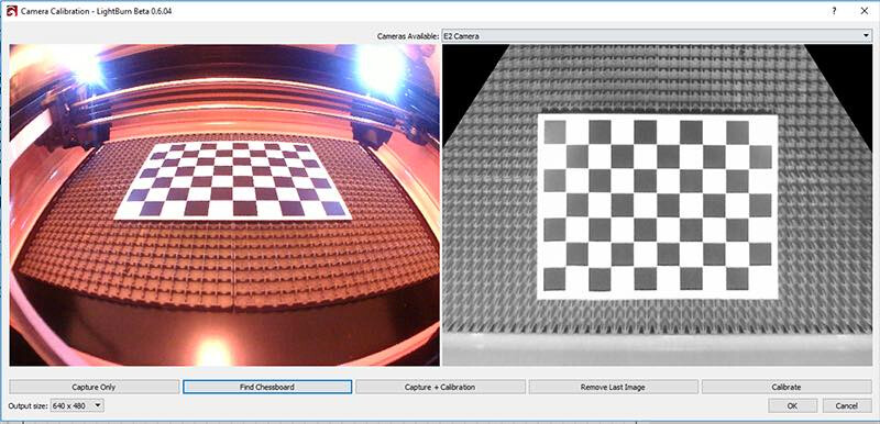
Did you have the pattern card on the bed of the laser when doing the lens calibration? If so, that’s the likely issue. The lens calibration has nothing at all to do with the laser, only the camera lens, and the big mistake everyone makes is printing the card at normal size, laying it on the bed of the laser so it’s the size of a postage stamp in the camera view, and calibrating that way.
When calibrating the lens, it’s much easier to just set the camera on the edge of a desk, hold the card on your knee at whatever distance you need to get the size in view to roughly match the preview, and capture that way. I’m going to be doing a video walkthrough of this before long, so we can replace the camera setup vid we have now. It’s long overdue.
If it removes this, yours should be simple:
1 Like
Is the square checkerboard pattern an option right now? I thought the polka dot was a strange choice as it seemed to lack exact features to lock onto with precision.
Also, can I just create a larger card? 1600mmx1000mm bed here. Taking the camera off its mount and un-zip-tying the cable is going to take awhile. How critical is it to hold the card at the right distance and angle?
The distance and angle are well-controlled if it’s still on the bed, so making a larger flat plywood test card sounds like an ideal solution. Will the current release of LB recognize the checkboard if I give it that? Is there a place I can find that specific checkboard pattern?
I did cover the unused honeycomb.
(I had this posted as a new thread, I think it’s better here. I can’t delete the other thread though. Still need help!)
Been working to get better lens cal in my 16MP Arducam. Great camera! But my first cal was a bit dicey- you can adjust the X/Y offset/width to dead nuts on any 2 points on the bed, but other points were often 2-3mm off due to limitations in the lens cal. Much more so near the edge. Glued the card to wood, no wrinkles, focused camera, covered the honeycomb.
This is with the door interlock disabled and the door left open- plus a lot of the error was left/right offsets so zero chance it’s the door stability. I covered the honeycomb. Other complications- this is a 1.6mx 1.0m bed, it’s huge. The test card is small. Also the 16MP Arducam was supposed to be 105deg FOV, but it appears wider than that. At the time, I was forced to use the set screw for the lens that came with it- those are awful. They’ll crush the bottom of the tube without really locking the lens focus. And when you do try to tighten it, it shifts the lens and throws off the focus you just set, and shifts the alignment too. But I changed to a threaded locking ring and it’s great now!
So I took the camera off, put the test card on the floor, played with the lighting, but got mediocre scores. Better than 1, but rarely near 0.3, again, limited accuracy.
Next I took some Youtube advice. Lifted the card so it fills approx ~1/3rd the screen width, and tilt it so its normal vector points to the camera. Bad scores or failed detections ensued.
I was concerned it’s somewhat out of focus at this point. So I got white posterboard, lasered the pattern into it, and laid it on black foam-core board, WAY bigger than the printer page, and filling 1/3rd the total FOV width when laid on the bed where the camera is focused. I think it looks pretty good now, close to the “do this” picture. Tried it with interior lights on and without. But, ZERO recognition going on most of the time, and when it did score, it was a high number. Tried covering up the black sides of the card too, again no joy. At this point I can’t see any benefit to removing the camera again to try to cal off the machine with just the larger card.- there’s nothing about the machine likely to be interfering. Anybody see something I don’t? Why is the cal so unhappy?
BTW, I have a zoomable M12 lens on order (you need to get the non-“IR” one, which would mean it has an IR cut filter so it’s not flooded with invisible light that maps to a wrong color. I don’t think the Arducam has a cut filter with a regular lens. The zoomable lens should hopefully still have enough FOV to see the whole bed, but if I can match up the FOV to JUST the bed, the image resolution per mm is going to be much higher all over.
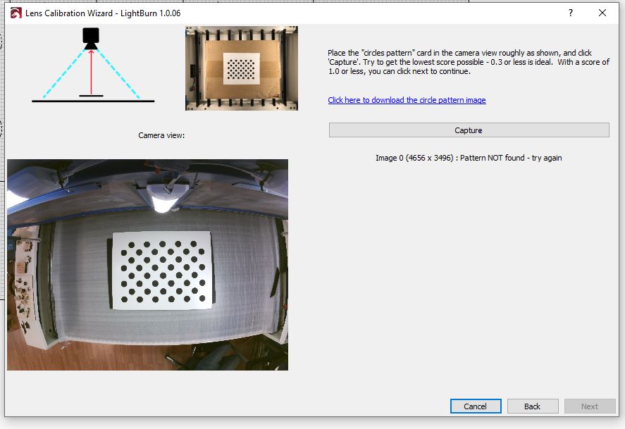
What do I have left to try? The honeycomb is covered, the lighting is good, the XY placement is good, the orientation is normal to the camera, and the size in-field looks perfect. And it’s getting poor scores or often nothing.
The only thing I have left is maybe the floor underlayment foam I used to mask the honeycomb is not a clean white. This seems unlikely, and I didn’t get “great” scores when I had this off the machine
Can I use a checkerboard, or does that require a different config in opencv? I did try with a 8.5x11 printout (can’t laser out a large one from posterboard since it will fall apart) and got no recognition
Hey is there a way to run OpenCV independently/externally with “whatever method works”, and get a file I can enter into LB’s machine config? I do see the numbers inside the XML file. I’m guessing this will work since LB has no reason to format them as anything different.
Well, I retried and for no logical reason I started getting good <0.3 scores this time, and it’s looking much much better! This was with the normal-sized card on the bed- and, actually, leaving the honeycomb UNCOVERED.
I was tilting the card on the edge shots to try to make the normal vector of the card’s plane point to the camera. Sure, that would help- but I got an unusually high score this time on the first shot too, and that’s at the center and doesn’t tilt anyways. Still, was so much higher score.
Still, can I use OpenCV to get better parameters? It looks like LB hardcoded in card methods that might perform well for 8MP cameras on like 32" x 18" beds.
I see OpenCV supports chessrboard and circle patterns, of different array sizes other than this 9x6 array. With 16MP, I think I could get better lens calibration with a chessboard pattern with a larger array. And/or taking more than 9 perspective shots. This is a fixed-focus camera and if I’m using a 8.5x11 printer sheet, it’s best focused at the bed’s distance but then a 3x3 grid of sample shots of the sheet leave a lot of the FOV uncovered. If I lift the sheet nearer to the camera to make the printer-sized paper take up 1/3rd the FOV it will be somewhat out of focus.
I think I could get better cal on this high resolution, large-bed situations with more than a 9x6 and more than a 3x3 grid of perspective shots, and that checkerboard image. So, I’m hoping I can get into running OpenCV, change it to use a denser chessboard matrix, more than a 3x3 grid of perspective sample shots, thus get a really thorough map of the lens calibration, and cut-and-paste the precise parameters into LB’s machine .lbdev XML file?
From reviewing the article here it looks you may be able to run this externally. The sample configuration file looks like it could be readily adapted to LB syntax.
Hey I didn’t mention it, but I see there’s a limiting factor here I saw- on a big machine like this, the door may not be hinged at the back of the bed.
While on the machine, we can’t get a card near the field of view at the top of the screen. Granted, we can’t image that area anyways, but it might confuse the overall lens calibration to some degree if it never had a good sample view from that region.
I ran it again and got pretty good scores.
One takeaway- the honeycomb being uncovered was NOT a problem. In fact the opposite- white underlayment foam covering it got no recognition at all. I think the pic I gave above shows no glare problem blinding the camera- but it fails completely if it covers the honeycomb.
I’m a bit confused though in that I got its lens calibration to appear quite flat. And I ran Alignment and was accurate better than 2 mm on most of the bed.
Then I came back later and we tried to demo it and the camera is way off, like 10mm. Now I’d readily blame the lid not sitting in the same position, but the error was mostly horizontal, not vertical.
The camera is VHB taped into place, it’s very solid. Its pivot mount is pretty tight, but that’s beside the point when the pivot would shift the picture up/down not left/right.
And I checked the Camera Control did NOT have anything entered in X/Y size/shift, both before starting Alignment Wizard and after.
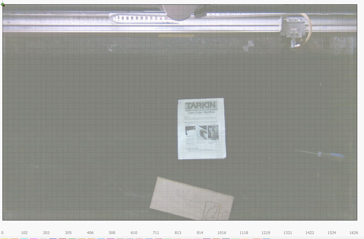
Bad news, a setback. The bottom line seems to be the Arducam 16MP which is sold with a 105deg lens has WAY too wide of a FOV for even my 1600mm x 1000mm machine. A very significant portion of the pixels are outside the bed and useless… The ultimate bed resolution is disappointing- what’s more, the OpenCV method CANNOT remove enough distortion for high accuracy.
I bought a 5 lens M12 “Arducam lens set” but found they do not work. They’re designed for a smaller image sensor. The 90deg had black areas in the corners, the 70deg FOV was looking like an EXCELLENT choice and would dramatically increase resolution, except it bottomed out slightly short of actually getting into focus.
SHOPPING FOR LENSES
OK these are M12 lenses, but FOV is not the only parameter, and it’s often not stated in FOV. First off, simplest thing- the 16MP does not have an IR cut filter. You probably do want an IR filter, but that’s up to you. If you don’t, you have extra light that you can’t see getting blindly mapped as “purple” and thus the colors are a bit perverted and vary greatly. So you need an IR cut filter in the lens. Unfortunately terminology did the WORST thing- an ad saying “IR” may mean it has an IR filter, or the opposite, it is for a night security camera designed to work with IR so it does NOT have a filter. “NO IR” is equally ambiguous.
If you have a pic of the lens at a specific angle, the back of the lens will appear pink if there’s an IR cut filter.
OR, yet another option, you can also get a new M12 mount with 20mm hole spacing- and you may need to- that is the correct length for the lens, AND has an IR cut filter built into it.
What I see is the 16MP is a notably larger imager. It is “1/2.8inches”, aka 0.357", aka 9mm. OK that’s straightforward to search for, right? Sadly, no. Well, FOV is sometimes stated as degrees, but also common to only give the “focal length” of the lens which also sets FOV. Well, be careful- fov 90 deg=“2.8mm lens”, 75deg=“3.6mm lens”. DON’T get confused, and your search attempts may get foiled- searching for “M12 2.8 lens” may get you ANY FOV lens made for a 1/2.8" imager, OR a 90 deg 2.8mm lens that will not fit this “1/28inch”/0.35inch/9mm imager".
THE M12 MOUNT COMPLICATION
I got the 16MP Arducam with a metal housing and a tilt mount, I found it tightens sufficiently to use as a housed camera. However, the M12 thread is part of that metal housing, and it was TOO FAR OUT for some lenses. The 90 deg (which was for the wrong imager size though) couldn’t screw in enough to get in focus. There is an M12 lens mount that you can put on the board that the 90 deg lens could get closer and focus with- BUT then it won’t fit in the case, and it’s just a bare board with no way to mount and angle correctly. I may have to drill out the case’s threads so it won’t interfere with the board mounted holder, except I don’t know if the board mounted holder is the way to go because I don’t have the right lens yet. But also, the M12 board mount comes with 18mm and 20mm hole spacings, the 16MP Arducam uses 20mm. They also come in metal vs plastic and different heights. I’m not sure of the height yet either, but the “long” one used in the steel case only works for its stock 105 lens, otherwise you need “something” shorter. But I still need room for a locking nut ring, which the Arducam DID NOT come with. Don’t use the grub screw- it doesn’t really hold the lens focus, it just destroys the thread and the mount and even pushes the lens off center…
So, off to search. M12 lens, with IR cut filter, for a “1/2.8in”/0.357in/9mm imager. I think 75deg=3.5mm is going to be ideal for my lid height and bed width. 70deg might lose visibility to the very extreme edges of the bed (no big deal) but the resolution with be amazing, like you can read text. I can also go for 90 deg=2.8mm. They may require an M12 board mount and drilling out the case but I’ll wait until I find the right lens first.
There are the variable-zoom lenses. I see ones meant for 1/2.7in imagers, which is “close enough” to 1/2.8in. The “2.8~12mm” type is supposed to be 90°~28° deg and we’re shooting for about 75 deg, and this could be amazing because any excess FOV really reduces the resolution on the bed. But there’s a catch- one, this is a physically large lens on a relatively tiny mount, and appears easy to bump and break the mount. So I think the solution will be to build a mount that instead holds the lens, and the board and camera float on back. Second, we’d need to look carefully if this can even mount on the lid so the head CAN’T strike the lens when cutting in front.
1 Like
Strangely I’ve found our Makerspace users are activating the camera with the lid CLOSED, with just the regular Windows app, to watch their job run. We never told them they could do that, in fact we haven’t even taught the camera alignment yet AFAIK. But they did find the camera somehow
I’ve purchased two of these - one you linked at the top of the thread, and another that’s a bare module, so I can try them here and see how this works here.
The checkerboard pattern was switched for the circles pattern relatively early on because the circles tended to give better results, and were recognized more reliably across a wider range of lighting conditions.
You should be able to just drop the OpenCV numbers directly into the distortionMatrix values and set whether it’s fisheye or not - LightBurn just looks for the numbers.
With a machine that size, you’re likely going to have better results with a head mounted camera - there’s code for that in the pending release. You don’t need to use a high res camera for this because it takes multiple images and stitches them into a final background. The maximum error is limited to the worst of a single capture, and you can specify the area to capture if you don’t want to wait for the whole bed image.
Lens calibration for this is identical to what’s there already, and alignment is a little different, but similar to the overhead cam alignment - it’s just tagging a marked pattern.
Interesting… should make for some dizzying mid-burn action videos.
Cool! It’s really amazing that you’re steering the dev effort to align with what we’re doing.
Note there’s a fixed and auto-focus version of the camera. I think the fixed is a much better idea.
BTW, I’d emphasize the need to get an M12 ring nut to lock the lens. Without it, it is loose, it rocks around, and the set screw causes the lens to shift substantially and actually crushes the lens tube before locking the lens firmly.
The loose shifting around was pretty serious on mine, and I wouldn’t even trust the lens calibration after that. Like I was zoomed in on something on the bed and the image shifted tens of mm when attempting to tighten the grub screw.
That probably means the second lens has likely moved laterally and angular, so its normal vector isn’t right and that will add some odd distortion to this. The locking ring preloads the lens threads evenly and it should be centered correctly.
I did detail the search for a more appropriate lens for the 16MP. Had to order from China, so slow boat. I should get them in a few weeks and will report the results. The things I’d recommend you order now because I’m like 90% sure they’ll work:
https://es.aliexpress.com/item/1005001349942062.html?gatewayAdapt=glo2esp&spm=a2g0o.9042311.0.0.105763c0VFoMI0
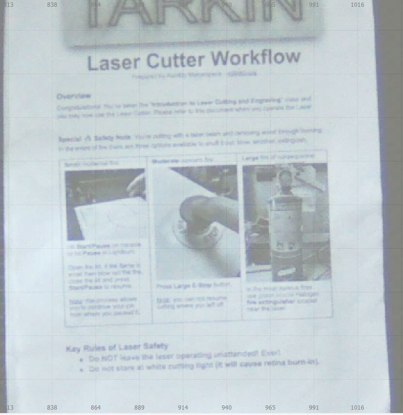
This is my view of a 1.6m x 1m bed now. It’s pretty sweet, I can read bolder text. It’s about 3 pixels per mm.
Really hoping the Custom Camera profile will be working soon! I had to kill the room lights to get this- otherwise the camera’s auto-exposure turns the gain way up to bias for the black honeycomb, as it is the majority of the field of view. The white paper will be overexposed and not a useful image
This topic was automatically closed 30 days after the last reply. New replies are no longer allowed.