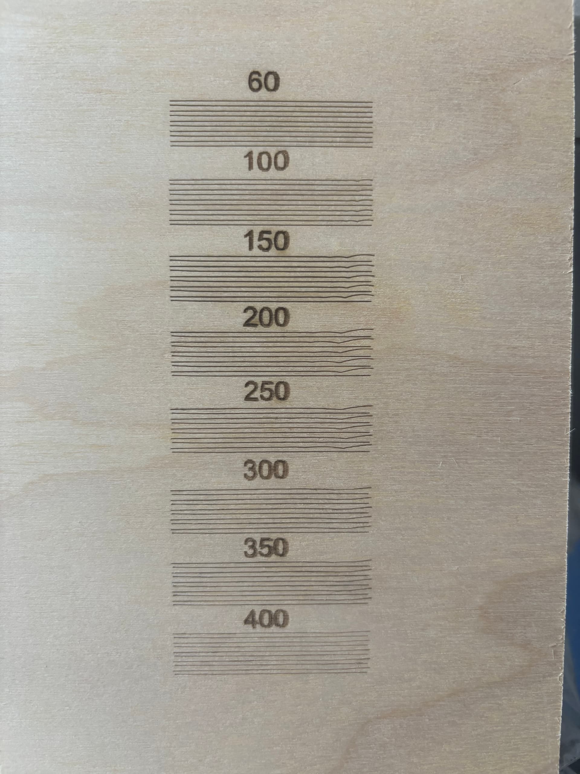
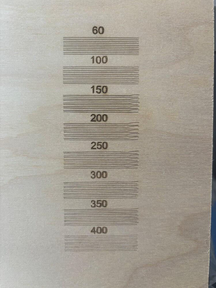
Hey all. Bought a new 90W CO2 Laser from Monport. Works great until I enable Bi-Directional. I’ve had experience adjusting the scanning offset with my Diode laser, but this is a first with my CO2. I started at 60mm/sec and increased by 50mm/sec. However, at 150mm/sec, I start getting wobbles and it magnifies at 200 and so forth. I have included a picture of my test cuts. I have verified that the machine is square and I have adjusted the belts. Not sure how to lower the acceleration, if that is even a possibility. Any ideas are very welcome.
Thanks,
Mel
I thought I knew, until I tried it:
Other than checking to be sure:
- The laser head is firmly attached to the X axis bearing carrier
- The lens is secure in its holder (and so is the holder)
- Mirror 3 isn’t flopping around
You (and I) may need to pick an engraving speed where the wobbulation isn’t a problem for a particular job, which isn’t comforting.
I did check the to ensure that the belts were nice and snug, the laser head was secured, and the lens and mirror were secure. But then I decided to run the cut about a dozen times and found that the wobbles are identical in size, placement, length. That kinda tells me that it isn’t something bouncing around for to be that consistent. And it’s worse around 200mm/s.
But I did notice that the lines are not alternating left/right in length. Looking closer, it seems that both sides of the first cut are shorter than the second cut, of which both ends are longer. And it continues that pattern. This is very frustrating.
I also just noticed that the wobble is only on the right side. The left side seems to be aligned pretty good.
When you’re looking at the flex of the whole machine, it will wobbulate exactly the same way when subject to exactly the same sequence of forces. In general, laser & CNC machines are great at doing that: run the same job twice and everything will shake exactly the same way both times.
The fact the distortions are not random tells you the machine is (at least) reasonably snug. It’s just too bendy for the forces exerted on it.
There’s a reason CNC machines intended for precise cutting aren’t screwed together from bent sheet metal and rubberoid belts. Of course, those machines cost far more than the lasers most of us have around, too.
Assuming you have a red-dot pointer on the laser head, park it in the middle of the platform (with the power on) and shove the head in all directions (by hand, without overpowering the motors) while watching the red dot. If the spot moves at all without the head feeling loose, you’re seeing how much the head / mount / bearings / gantry flex under the force you’re applying.
You’ll find doesn’t take much oomph to produce a visible offset in a spot that’s only 200 µm wide. The largest wobbles in the 200 mm/s group look half a millimeter off the midline. If the laser head flexes at the X axis rail carrier, that’s an angular error under 0.2°, which isn’t all that much in the scheme of things.
It definitely needs attention here, too. ![]()
Won’t help the wobbulations in the Y axis, of course, but you can crisp up those digits a lot.
I think that’s approximately “Don’t worry your pretty little head, everything is fine.”
From stories around here, tech support will generally send a replacement part when clearly shown the original is defective. Anything more subtle than “There is no power” doesn’t fit their script and definitely will not rise to the level of a warranty issue. There are exceptions, but expecting nothing generally does not produce disappointment in the results.
We’re pretty much on our own …
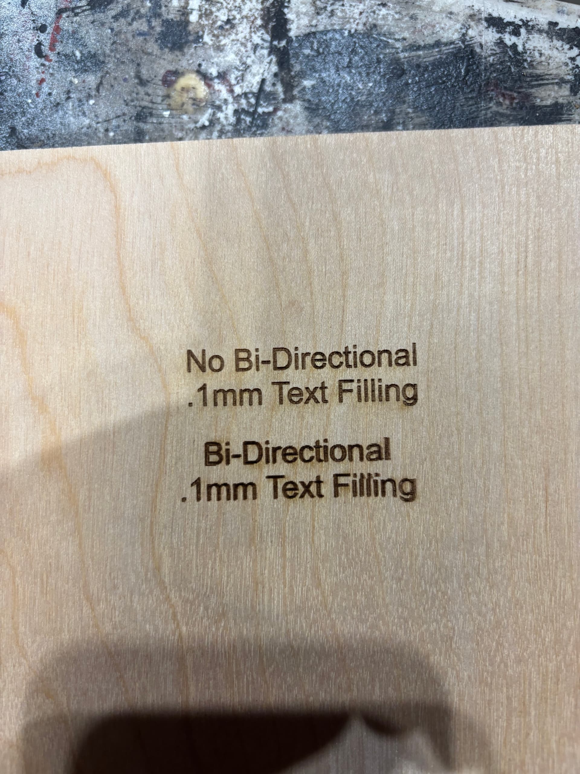
Several things stand out:
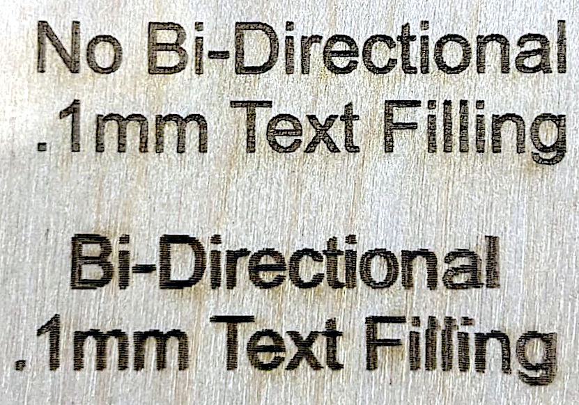
The bidirectional fill needs better Scanning Offset Adjustment, because the edges of those letters are ragged. The decimal point and dots over the lower-case “i” letters clearly show the problem.
Adjusting the offsets may also clean up the broken letters in the lower “Filling”, as the errors look like they depend on their surroundings. I assume it’s scanned edge-to-edge, rather than letter-by-letter.
It’s been difficult to do more scanning offset calibration at the 200 speed due to the extreme wobble. But also, where do you measure? The lines are alternating both ends short, then both ends long. There isn’t a measurement that I can get for both sides since the left side looks very close. I did attempt to measure the extreme wobble distance and divide by two, and lets just say the text was not legible.
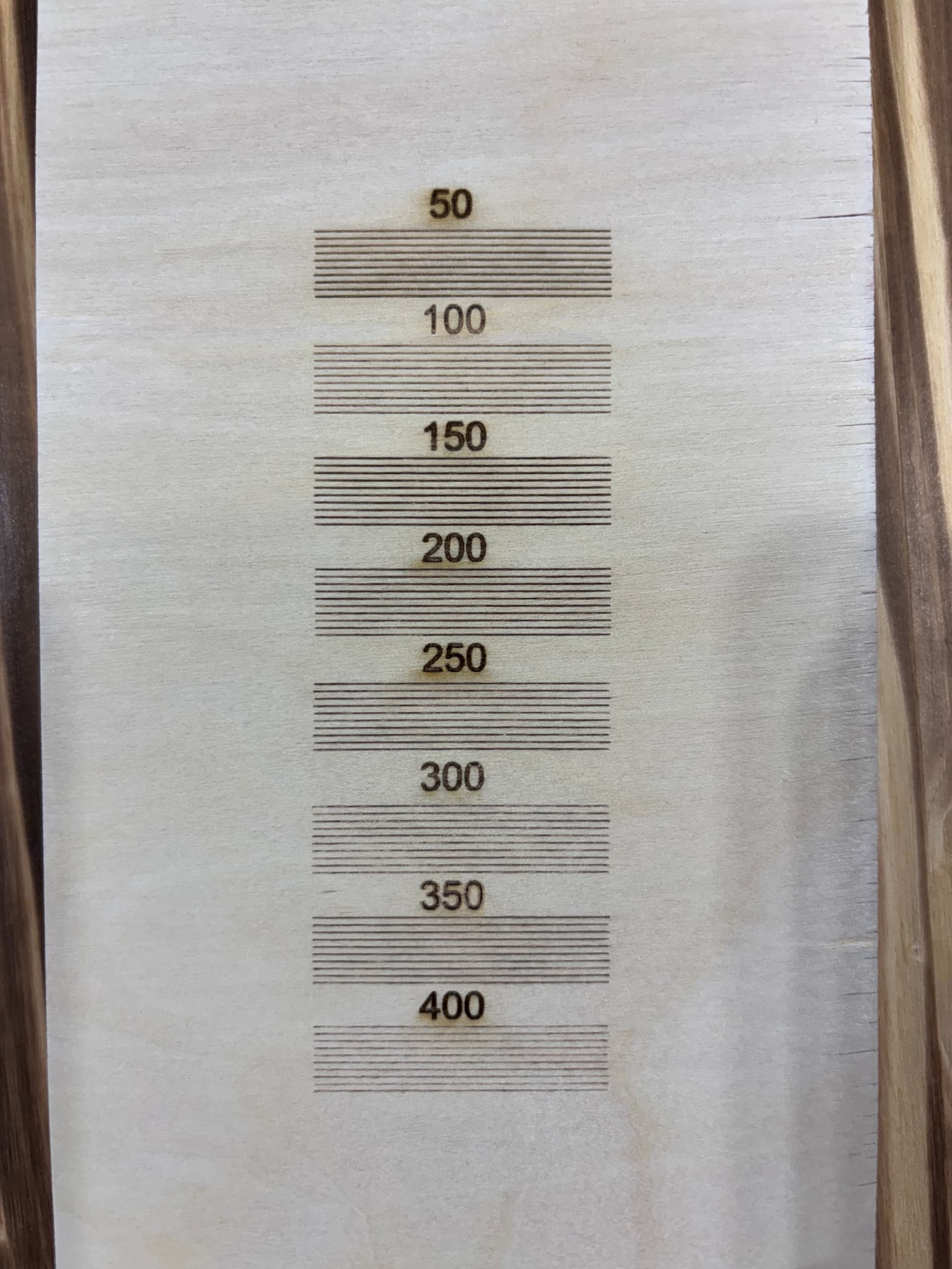
Do the measurements across the range of speeds from maybe 50 mm/s up through as fast as it goes. The power supply typically has a constant delay, so the offset distances will be approximately linear with the speed; remember to enter half of the offset between the ends of the lines.
The offsets in this test should work fine:
The laser head may be rotating left-and-right, as well as front-to-back, which will affect the results, but the offsets on the right side look usable.
I’m going through and rechecking everything. One belt on the left gantry was not as snug as the other two. Tightened that. I checked all my mirror alignments and they are spot on. Not sure if this is an issue, but the nozzle that the air and red dot attach to just bounces and wobbles all over the place. Not sure if that is how it is designed or not. But it has a tremendous amount of play. Normal?
The focus lens sits on the top of that assembly, which is one of the possibilities I mentioned earlier.
No.
Basically, anything anywhere being loose is a problem in need of fixing.
Given what you’ve found so far, this test pattern will be useful to identify more problems:
Scale it uniformly to fit the platform and run it as fast as it will go in Line mode with optimizations turned off and power set to mark a sheet of cardboard. Any differences from the design will be informative; a photo will let us look over your shoulder.
![]()
I’ve seen worse … on that very machine. ![]()
I would point out that painter’s tape is not a permanent fix, but you know that already.
I’ve already emailed Monport back with the results of my temporary fix and now need to know how to proceed with the permanent solution and fix. Sent them video of the very loose and wobbly tube assembly. We will see what happens next.
So, you will never believe the fix. Disconnect the air port from the laser head, twist the blue sleeve to tighten it up, and adjust the red dot emitter to the back of the laser head. 20 seconds and it was fixed. Tested up to 700mm/s bi-directional with no issues. I think they need to add a step in the new setup to check the blue sleeve for tightness. But at least it was an easy fix. I do appreciate all you help with this.
I love happy endings … ![]()