Autofocus re-connected, Giving it a try

Ok…AutoFocus Pen In Parts:

Actually got this one right…it is and Inductive Sensor, hence the 6-30v notation…
Looks pretty simple, although it was a pain to get apart…
had to put it in my Lathe chuck jaws clamp down and with another rod holder clamp unscrew the parts, as they used glue or locktite of some sort…

One thing I noticed is that there is an adjustment of sorts with the set screw…
the Sensor body is held in place with the set screw, and you can push it down
if you use a long thin ‘pin’ or something like that from the top…
As you can see the set screw indentation, when loosened it is free in the unit,
and you can move it up and down. So moving it down will help with the
long press throw some pens (I suspect) may have, as mine did.

Anyway… I think this will help folks that may want to experiment and adjust
their pen so the plunger does not have to travel so far to trigger…

The trigger is the simple long plunger screw ‘head’ that just meets up with the
sensor face, (BLUE) …

Kinda neat design actually…

Enjoy and share :slight_smile:


You have compelled me to dig into the wiring channel enough to completely expose the cable (*) on my sensor, which has, contrary to my previous findings, three wires:

  • Blue = GND
  • Black = signal
  • Brown = +24V

So it’s exactly like yours.

The setscrew dent in that poor sensor tube suggests mine requires more loosening than I’ve been willing to apply, but shoving it all the way down seems like a win.

Thanks for the investigation & report!

(*) During which, I dislodged the terminal block with all the home switch leads, thus causing a breathtakingly noisy dual-axis “crash into the rails” event on the next power-up. I will get you for this:grin:

1 Like

This was a good project to do, as I found nothing, anywhere about the autopen…
but it was a giveaway the 6-30vdc three wire…being inductive…

Yes the set scew is hitting right at the top where there is a plastic cap and a RED
Led under that, it turns on when depressed.
So you could use the top led as an indicator as you adjust the inside sense barrel downward before you tighten the set screw…

From where my set screw was, I could hve gotten at least 3mm more…

Waiting for my new pen to arrive… ordered two incase… :slight_smile:

I hate crashing axis !

Ok… Updated:

I decided to modify the original pen that I cut off my Monport 130W…
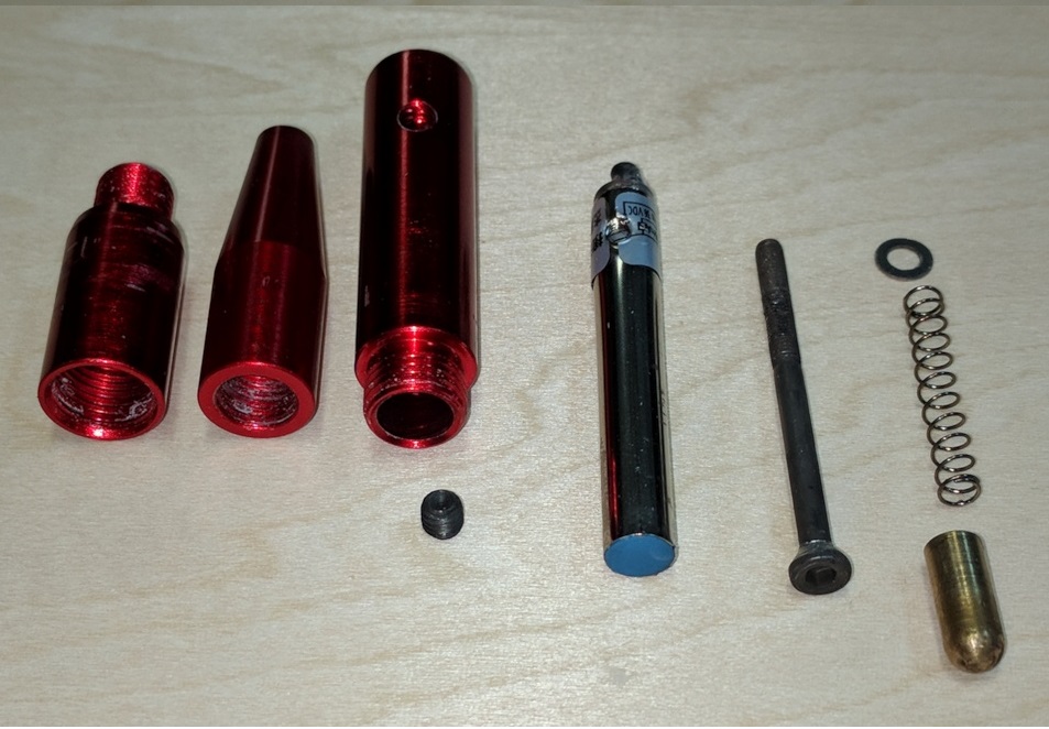
Here are the results: (in steps)

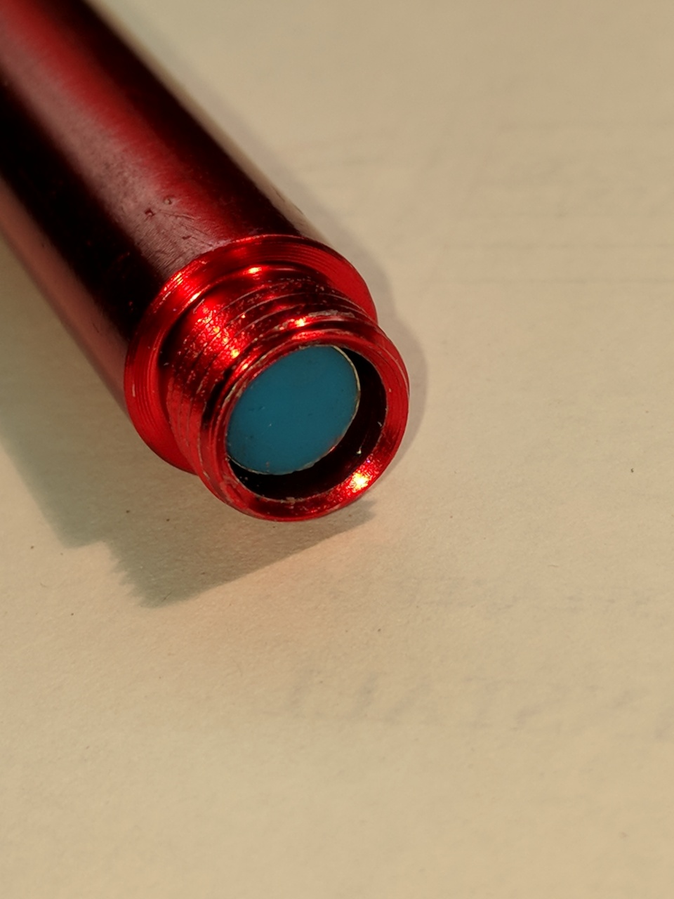
I modified the plunger top that makes area contact with the inductive sensor end (blue spot)

All the parts are shown:

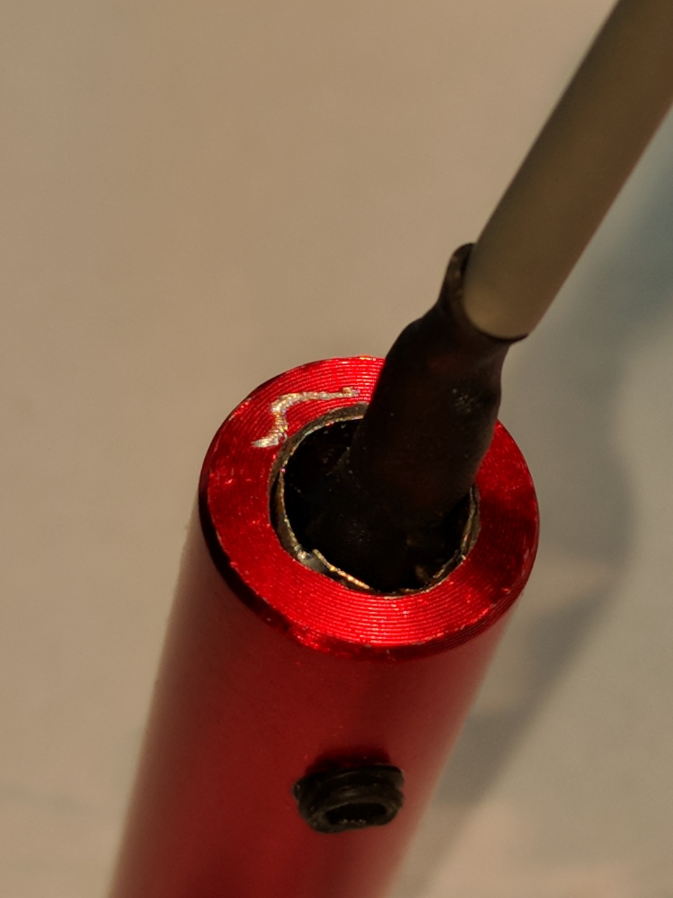
I replaced the cable on sensor module that I had cut off and also
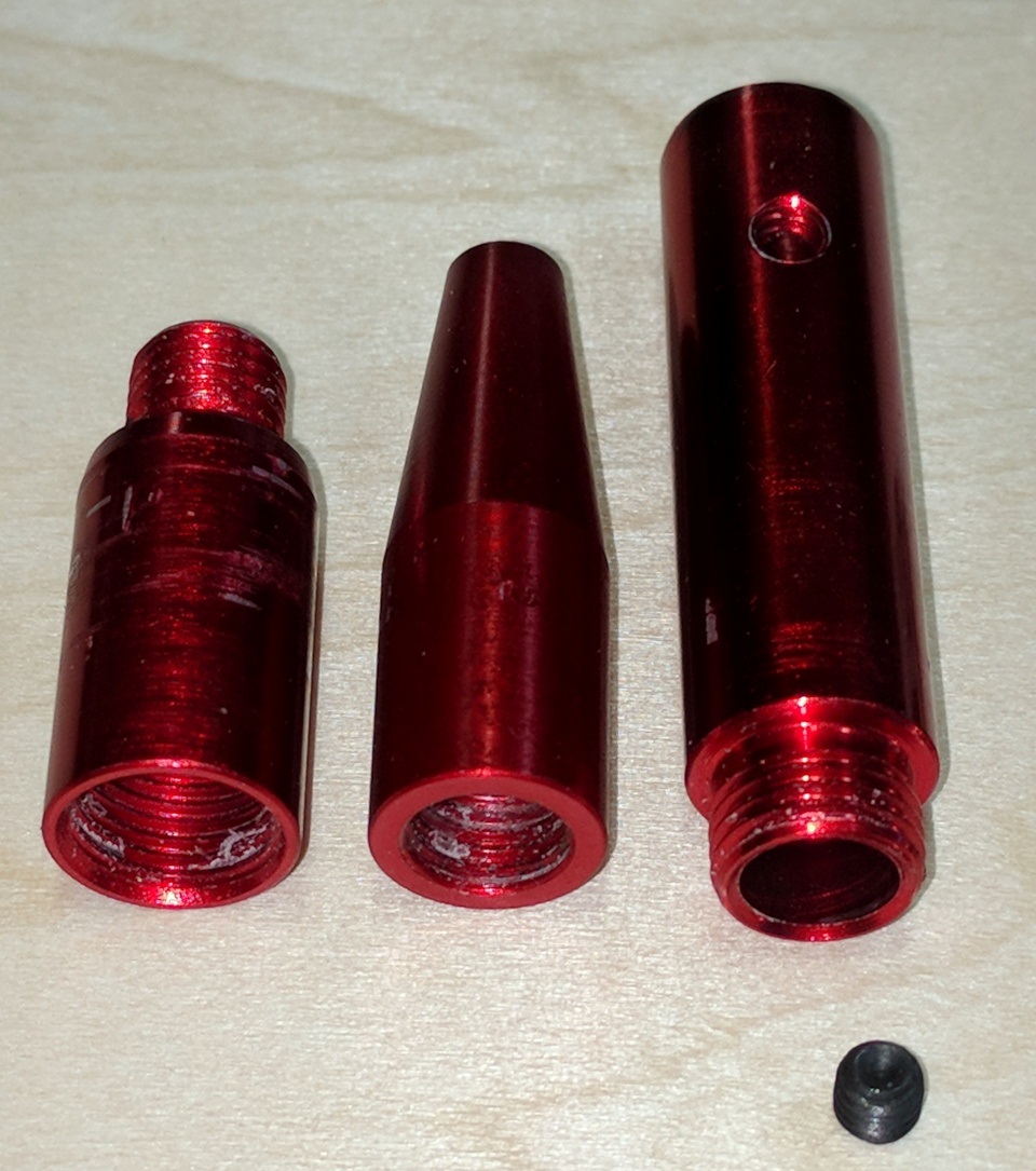
modifed the end of the top pen but opening up the hole to allow the sensor
to be placed in from the top. There was an internal lip that prevented you from just
pulling the sensor module out after removing the set screw…
This made it easy to work with…

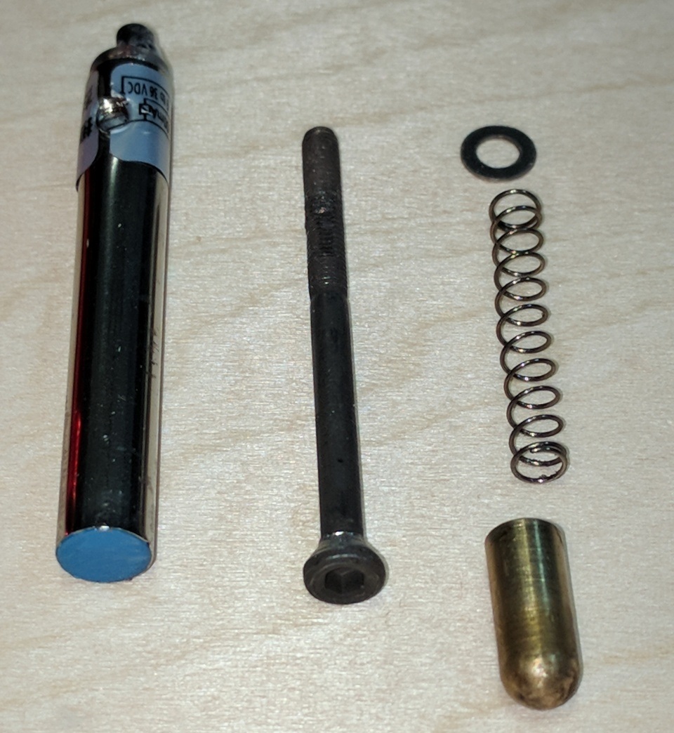
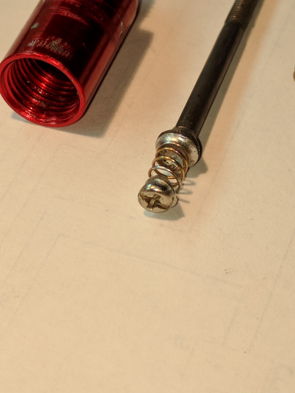
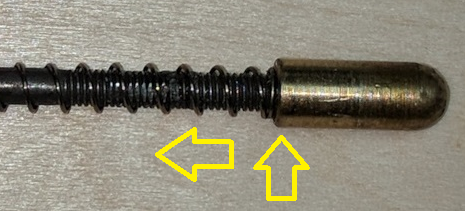
Next I added a spring and screw top, soldered to the top of the original plunger.
the screw top provided enough surface area to trigger the (blue) inductive area.
(this will become clear why it is needed below)

I took a spring from a typical ink pen and cut it and cut a screw top, clean
and soldered both together and them soldered to the top of the plunger at about
8.6mm length. This was experimental, had to adjust it a couple times for optimum length
but settled on 8.6mm.

I now inserted the sensor module back into the pen top (the piece with the set screw).

Pushing the module into the top I stopped just shy of about 2mm.
The top of the sensor stopped flush at the top of the pen body top.
Reinserted the set screw gently!


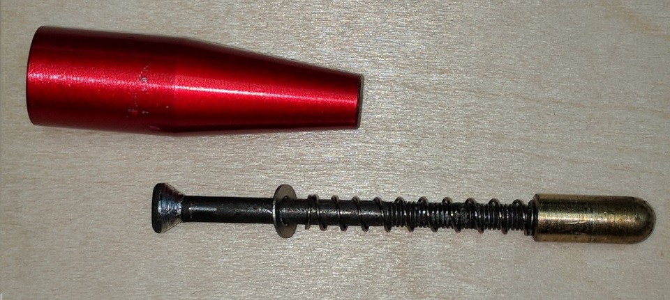
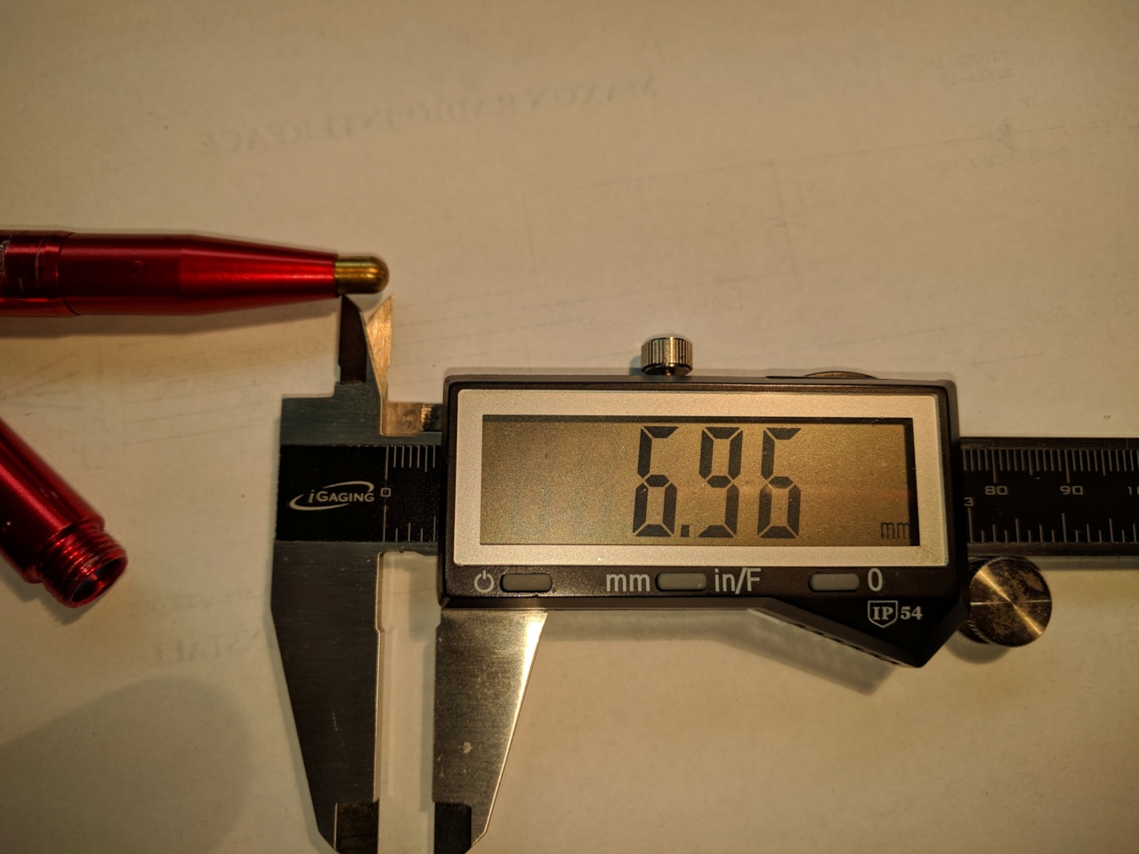
Reassembled the pen, and adjusted the pen plunger TIP by screwing to a length of about 7mm after assembly. this will take some tries to get it right.
I also used some clear fingernail polish as a glue on the plunger threads to keep
the plunger tip from unscrewing and changing position over time.


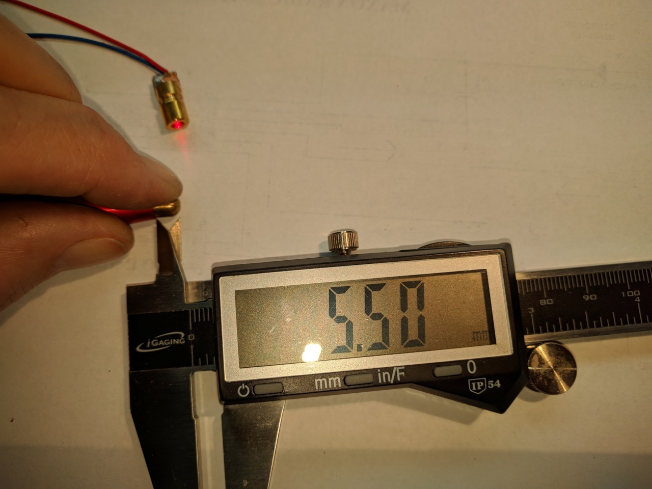
I used a handy laser module as the indicator for testing, (It was on my work bench)
I pushed the plunger into the body until the laser led turned on.
it was about 1.5mm into the body for the ON sense.
A big difference from the original travel, which IMO was excessive.

I pushed the plunger all the way until stopping and it was exposed about 2.3mm.
so this was an extra travel in the On position of about 3.2mm.
this extra throw was needed to allow some cushion in the bed ‘Z’ traveling up,
hence now we see why the extra spring and screw head were placed on the
plunger top. breathing room.

All this made the focus pen very quick to trigger on the initial contact plunging.
And still give some continued plunging with the added spring…
Have not installed on the Monport yet, but will be trying it soon with my hand
on the STOP button :slight_smile:
If you like this let me know !

Here is a video in action…you will have to download it and remove the .TXT extension to restore to a .MP4
You can see the actual travel and full travel and release.
Pen.mp4.txt (279.7 KB)

Just tested on the Laser… :+1:

Had a bit of a setback this morning after doing two sessions 45min ea.'of engraving…

Was checking my focal point, performed an autofocus and…
Head crash…!!!
I’ve become accustomed to keeping my hand on the STOP Button, this time it paid off…

was able to slide the acrylic out from under the head and lift the autofocus pen out of the way and turn the system back on…
Home position, then center of bed origin…

After checking the wiring found out the Brown(pwr) Black(out) Blue(gnd) had an issue.
First checked the 24v PS the Ruida connector… OK
then turned off system and ohmed out each autofocus pen wire to the controller and found the BLUE (gnd) wire was OPEN…
It happened after the two sessions of engraving ( X-axis ) movement.
Found that in the Chain Cable carrier, at the bend had stressed and broke the BLUE wire…
I’ve seen this before a number of times on equipement so not a surprise at all…

I put a new length of wire in the carrier connected everything up and it worked fine after about an hour…

I am thinking of using some larger diameter wire for the autofocus pen when I install the Beam combiner in a couple weeks… but for now it is working again !

This IMO is from the improper tight routing of the wires in the cable carrier.
For now all is good…

:+1:

OK final decision…
The Autofocus Pen is going into the bin…
After a couple weeks of ‘hand on stop’ each time I did an autofocus in LB
nervously watching the Z bed axis push closer and closer to the head…
I’ve had enough…
Worrying and measuring the Pen tip hitting a hold down magnet or worse the material I am working with ! No more…

With a few button presses on the Ruida keypad I have up down control and that is very reassuring…
It was fun going thru the exercise, but the after affects of the stress is not worth the very small benefit.
Especially since changing lens, which I do, not often, requires a complete re-setting in the LB Machine settings to tweak it each time. eh! Done…

I may look into an indepenant Z-axis UP /DOWN button on the chassis as some machines have for convenience of not pushing the Display panel buttions…'Another Project… Maybe !

Most of the people messing with these have come to the same conclusion.

:smile_cat:

Yes I can see that, us New users have to discover a whole new world of activities…