I really have to give it a bit of time to think about it, because i use the same extraction systems for both CO2s, Fiber and UV Lasers. They all share the same inline fan but have a system of blast gates to control the flow to whatever is working.
I used the same Optocoupler Isolation relays for my CNC Plasma table for the torch ohmic sensor circuit and it worked great. They come in different operation voltages (5, 12, and 24 volts) to work with the controller board power. Using the low input for the input trigger between the torch tip and table ground.
Go all in and use the Arduino to detect which device you’re using and have it open/close the gates appropriately!
2 Likes
The Arduino has multiple analog inputs, so multiple PWM signals can be input & control the output to a single exhaust fan. Just need to modify the code to monitor each input.
Let me know if help is needed with the coding…
1 Like
now that would be fun to have…
Have to get into that when i have time, gotta study the boards of the lasers to know the ports i can use for the signal of when it starts working and give it a timer to stop.
Im currently running 1 CO2 with a ESP32 with FluidNC and a 100W Fiber JPT Mopa and a 5W UV JPT Seal both with BJJCZ boards.
Love this thread. My challange is finding the signal from my Falcon2. I had thought about the current sensing relay before you mentioned it. I am in process of building my new enclosure now, and would love finding that signal connection - any help??
The cable going to the laser head should only have three wires. 12 or 24v DC, a ground, and the PWM signal wire. Trace it backwards from the head. I’m powering the Arduino Nano from the Lasertree K60 adapter. There was an unused 12v/ground connector on it. The “VIN” pin on the Nano needs 7-12 volts, so that worked out perfectly. Before connecting to the Nano, put a meter on whatever source you’re going to use to ensure it’s not more than 12 volts.
So far, the automatic exhaust control has worked flawlessly. I’m happy to eliminate the step of setting the countdown timer.
In a somewhat weird direction, I’m likely going to add a low end aquarium air pump to my air assist tube and connect the power to the exhaust fan circuit so that it runs whenever the laser is firing. The reason for this is to have some air exiting the nozzle when the air assist is not needed to keep smoke from traveling back up into the nozzle and dirtying the laser lens. I figure it would take very little air to accomplish this.
OK Doug - with that thought in mind - what I hear you say is that the fan doesn’t come on until the first laser shot is triggered, and then the fan ends it’s run when the timer times out.
The reason I ask is my fan has a start up time, which is about 15 to 20 seconds. (I know - sounds weird but it is what it is).
EDIT - although I could inset a momentary contact switch to start the fan circuit and then let it do it’s thing.
Correct. The exhaust fan starts the moment the laser receives a signal to fire, then turns off 60 seconds after the laser last fires, which is enough time in my case to flush the smoke out of the enclosure.
1 Like
The cable going to the laser head should only have three wires. 12 or 24v DC, a ground, and the PWM signal wire.
This might not be that simple on my case with Fiber and UV lasers, with the CO2 is much easier to implement.
In a somewhat weird direction, I’m likely going to add a low end aquarium air pump to my air assist tube and connect the power to the exhaust fan circuit so that it runs whenever the laser is firing. The reason for this is to have some air exiting the nozzle when the air assist is not needed to keep smoke from traveling back up into the nozzle and dirtying the laser lens. I figure it would take very little air to accomplish this.
I have this setupd on my CO2, an aquarium pump with a thumb regulator that’s always on when engraving to prevent smoke from fogging the lens and then i have a solenoid valve to contro high pressure only for CUT layers. Has been working flawlessly for a couple of years now.
1 Like
The Arduino Nano has a mini usb connector used to communicate with & program it. It can also be used to power it. It’s a 5 volt connection, so a simple 5 volt wall adapter can be used to power it.
I don’t know if this answer is for me, but in the case it is. Im just concerned where to get the signals from BJJCZ boards that’s says laser is working
Which version do you have? I’m seeing a few different ones on their site.
Original Standard BJJCZ board for EZCad2. I don’t know the correct model number because I have yet to open my Galvos cases just haven’t had the time yet
If this is your card:
I found this pinout document…

I’ve only worked with diode lasers, so I’m not familiar with all of these connections & what exactly they do. There appears to be multiple possibilities on the CON2 connector. Hopefully someone with knowledge on this will come in.
1 Like
Well the outputs are TTL level so they will be 5V.
That’s what I assumed too. I airways error on the side of caution, so I would start by using a meter to insure its no more than 5v, then monitor it with the Arduino to obtain the max voltage or range. The code can them be fine tuned.
A level shifter as a precaution or a resistor ladder to step to 3.3v logic. I am on the side of level shifter since they often use optoisolator
1 Like
A simple voltage divider will get you there…
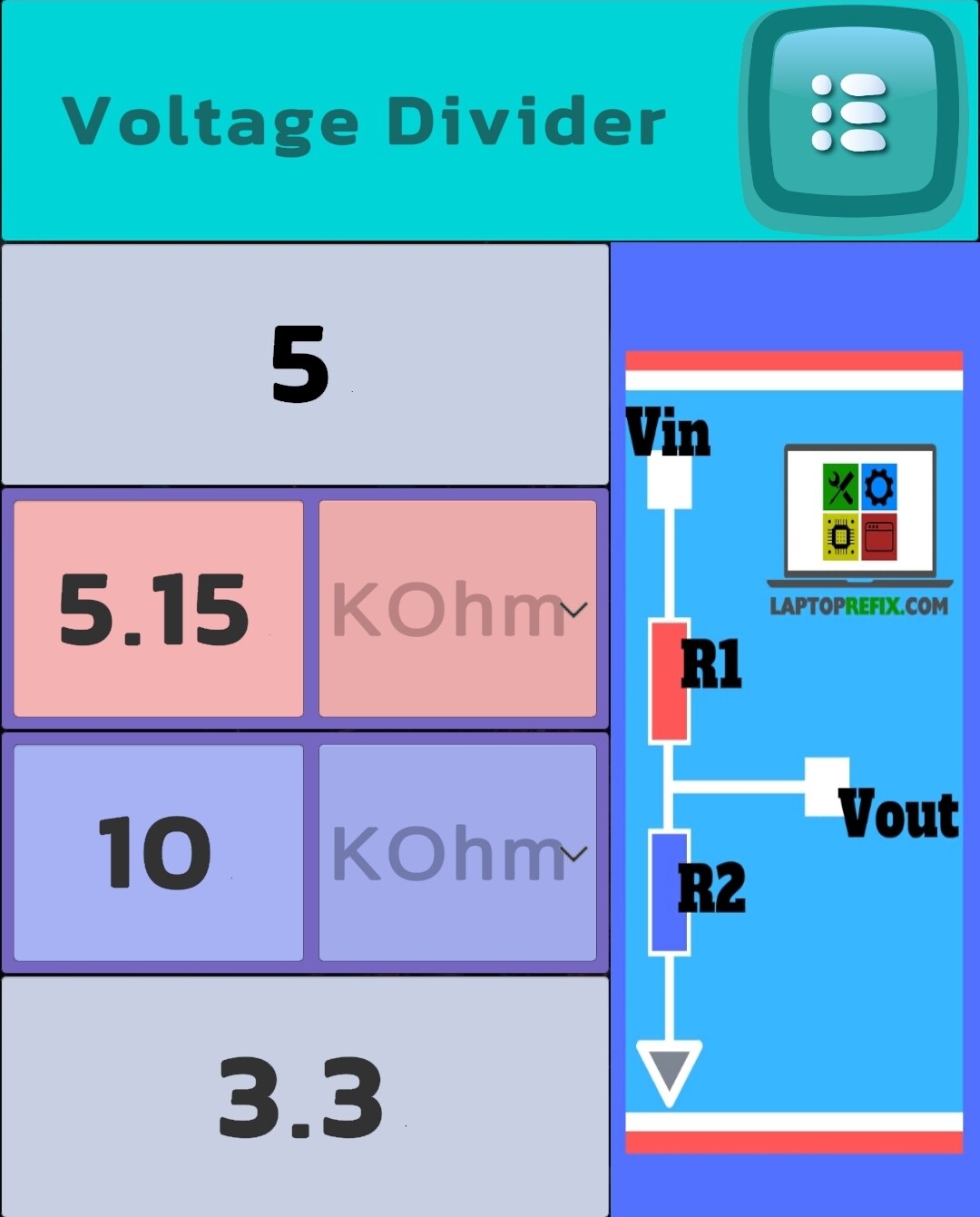
The Arduino Nano is fine up to 5 volts on its inputs. The Arduino Pro Mini is 3.3 volts max.
I would recommend starting with a meter, then a voltage divider on the Arduino input until it’s determined the voltage range that can come from the controller board.