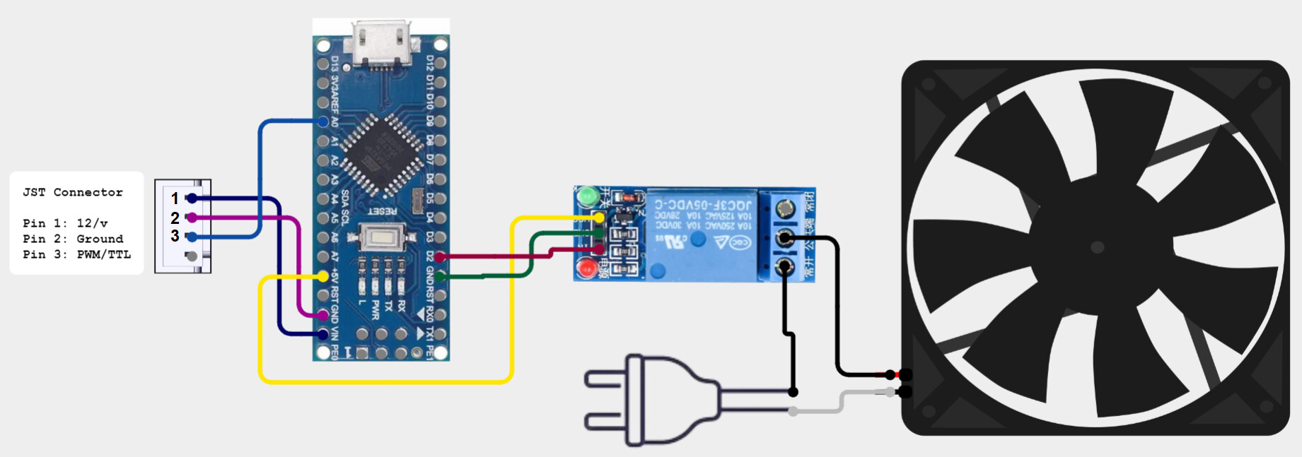
I finally focused my brain today on creating a circuit to automatically turn on the cabinet exhaust fan when the laser starts, then turn it off one minute after the laser is finished. I have a home-built laser using a MakerBase DLC32 v2.1 controller. I got into the “Arduino” hobby a few years ago and figured that I’d find a solution there. Sure enough! Using an Arduino Nano microcontroller, a 5 volt relay module, and a few lines of code, I have it up and running! My exhaust fan is quite strong, and 60 seconds is more than enough to flush the smoke and stink after the laser’s done.
The code, in a nutshell, monitors the voltage of the signal voltage coming from the laser controller. It’s “0” volts when the laser is not running, and a varied voltage up to 5 volts while it is running. The threshold of “0.05” volts has worked fine for my setup. The program keeps track of elapsed time and uses that to turn off the exhaust fan 60 seconds after the laser turns off.
The only thing left to do now is to design and 3D print a enclosure for the Nano and tidy everything up.
I thought that might be what you’re using. Shoot. I have a couple, but we just moved in October and they’re still hiding in a box, somewhere in the back room. I guess Amazon gets a couple more dollars today.
Thanks for your reply! I just might rig my exhaust fan up similar to how you did yours. It’s a really good idea!
I’m also adding a micro rocker switch to bypass the control signal & just run the fan. I also use my laser enclosure when I paint or polyurethane small items. I stick them in there to dry & vent the sink outside.
My laser is home built. I started with a small Two Trees unit, then used the hardware from it to build a much bigger unit. We had our ancient oil furnace replaced a few years back & went full electric. I connected the laser exhaust to the old furnace vent connection & everything vents up the chimney!
Looks like you’ve set your exhaust system as a downflow built into the table. That’s a good way to keep the ducting out of the way. I like the ide of using existing ducting to exhaust from your workspace. We rent, so that’s not an option for now, but if we’re ever able to buy a place of our own, I just might steal that.
I also built my machine. It’s my first and like I said, we’re renting, so it needs to be compact and easy to relocate. It’s sized to fit a card table. All brackets were designed in Solidworks and printed in PLA. My card table has seen better days and the top sags, so I created a work surface that I can attach the laser to so it doesn’t get knocked around.
For now, the vent hose is just thrown out the window and the gap is filled with an old blanket in order to keep winter outside. Plans are to make an insulated window-gap-filler-board with a dryer exhaust louver, but we’re moving soon and I don’t want to have to re-make it, so it’ll wait until we’re settled for proper sizing.
I’ve considered getting an exhaust fan similar to what you have mounted under your table. It looks like what I’ve seen used to assist dryer exhaust on long duct runs, and I’m assuming that’s the fan that started this whole conversation.
If I could make a suggestion for you to improve your exhaust airflow: Change that collapsible dryer duct out for solid ducting as soon as you can. The ridges create a LOT of turbulence within the ducting, drastically reducing airflow. Your fan is fighting a lot of back-pressure over that distance. It’ll also be a lot quieter. I bet you could cut your exhaust time by half as well! (I’m a professional appliance repair tech and run into a LOT of dryer airflow issues with that collapsible tubing for that same reason!)
My original setup was much smaller in my office. I used a decent volume “squirrel cage” fan connected to a piece of vinyl wood via two 1.5" flexible hoses. For what I was doing back then, it was sufficient to vent everything outside. Our windows slide vertically, so it was easy to get and keep a good seal.
I bought a couple of 3D printers right before the pandemic broke out. All of the black plastic in the picture is from my printers. It’s cool to be able to use one hobby to build another.
That relay board is commonly available on Amazon and Ebay. Look at the voltage and current rating, that one claims 10 amperes at 120 volts. Id be cautious running certain loads such as a heater, fans would be fine.
PVC would be okay, but I think it would be much heavier and quite a bit more expensive than the sheet metal ducting that you can find at any hardware store.
Also, to save on print time, elbows can be purchased as well.
Thanks! I ordered them earlier and they’re already on their way from Amazon. I actually found some that host a pair of relays that can be controlled separately but are mounted on the same PCB, which will suit my needs even better than the singles.
For those that are not comfortable with Arduino you can do this by just using current sensing relays which also come with built in timers and basically do the same thing, they cost around 12 to 20 usd and you can chose the amount of time you want the relay to operate for after the current ceases. Principle is the same you just dont need a Arduino to do the sensing and timing for you… Just search current sensing relay on Amazon. They can run most amperages up to 30 amps AC
I modified the circuit a little, adding a SPDT toggle switch. I also use my laser cabinet when I paint or polyurethane small items. I stick them in there and run the exhaust fan to blow the stink outside. I forgot about that when I first created this circuit. Flipping the toggle switch bypasses the input coming from the laser control board and just runs the fan.
indeed they do just search for current sensing relays on Amazon or AliExpress, make sure you get one with a good amperage and with a timer as not all have a timer, I use them a lot in my work and the normal relays, in fact my whole control board on my laser is powered by low voltage relays No high voltage is actually touchable on the outside of the cabinet as its all metal I wanted double protection and if for example you had wet hands and touched the control panel /laser unit etc you could in theory get a shock but by using relays powered by 5 volts DC its virtually impossible because of the protection relays afford with opto couplers. That and everywhere is earthed/grounded well and checked . Doing it this way is similar to industrial wiring, all machines are high voltage 3 phase but all the controls tend to be 24 volt PID controllers, I haven’t gone that far !
there is even a couple of pneumatic ( bottom right of control panel box inside ) relay valves to control the high and low air pressure for engraving and cutting, it knows how to switch using the pinouts on Eric’s board and switches on the control panel, It just switches over in the Lightburn options for air. M7/M8 ? I cant remember .
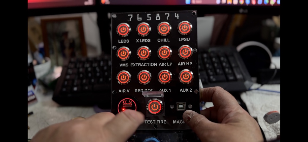
Also in the wiring you see buck converters to supply different voltages to different kit and so on, the led switches on the front are two tone, Red off and green on, unlit all voltage is off at the EMI filter so nothing live and safe to work on. There is also a cabinet switch that kills power via a relay in case someone opens the bomb bay doors! When I built this they did not sell high amperage led switches like this, now they do so if you dont mind 220 volts on the control panel you do not need the relays as you can buy 220 or 110 volt Led switches now.
It was a labour of love but worth it I felt, the numbers on the front panel between the upper and lower panel are Star Trek related, if your into the background of StarTrek and how it develops now the engraved numbers will mean something.