Hi Cees, I don’t know if this is a good news or not for me because in the meantime, just to test, i ordered another brand new controller ( this time a 6445G version) and with your post you demoralized me  … in any case i see that you have the lmt polarity in Positive… now my question to you is : do you have limiter NO or NC type ? because mine are NC and I must put the lmt pol in Negative this is the only difference that I see between me and you due that you told me that you left the wiring inaltered.Instead it would be very fine if you remember what you did to solve because from my side the Ruida technicians, Matt of MW Laser (one of most expert of Ruida controller) and myself we couldn’t solve the problem…
Thanks
Regards
Giuseppe
Guiseppe, I am so sorry! I intended to help not demoralize you 
Although I would be lying if I would say I didnt have my moments of despair over the last days to get this thing to work properly … I am a long way in but still a few key issues to solve… but that’s for another post where I have to call out for help.
My limit switches are NC and show as triggered in the FUNCTION+ menu (see photo)
What I do recall having done was a factory reset. I had changed so many settings without knowing what I was doing (my Chinglish isnt what it is used to be and I am a novice in laser cutting/engraving) that I needed a clean start. From there I set the Limit Switches, the Dir Polarity and the Keying Direction (and a few other things I dont exactly remember) and the homing and page orientation worked from there
Keep up the hope Guiseppe… it will work in the end (I hope for myself too  )
)

I am still convinced there is a configuration issue we are missing, seems supported by @Cees response. It’s always too bad when you fix something and you don’t know what you did… been there done that. It may be something in the S model that isn’t in the G model.
There are multiple combination of ‘which way’ a motor can be driven, most just inverting the signal, it seems. It has a tendency to be a bit confusing.
Your switches being NC should not make a difference and must be working or the Ruida could not home properly.
Maybe a better question for the Ruida people and Matt is
“How does it know which corner it’s in (or home)?”
This must be a configurable option.
I’ve ‘seen’ them in at least three corners as ‘home’.
What are you going to do with the other controller? I’ve thought about modifying the little machine, but it’s really more of a cnc that I use for pcb and such. If it needs a home… 
Keep this stuff in perspective. At least you are ‘vertical and ventilating’, some of the other options aren’t as good. It also seems there are probably configuration options we don’t know about or can access. Working with this stuff, the manufacturers seem to not tell everything they know.
Take care.

@jkwilborn , this morning Matt sent me a new firmware 26.01.16 but didn’t it the difference. If Matt had known how to change the quadrant he would have told me immediately and I don’t think even those of RUIDA know it otherwise they would have told Matt. About my controller S version… this is new (3 week)and i could ask to send back it and replace it with other… but until i don’t try the G version that is arriving i will be in stand-by…
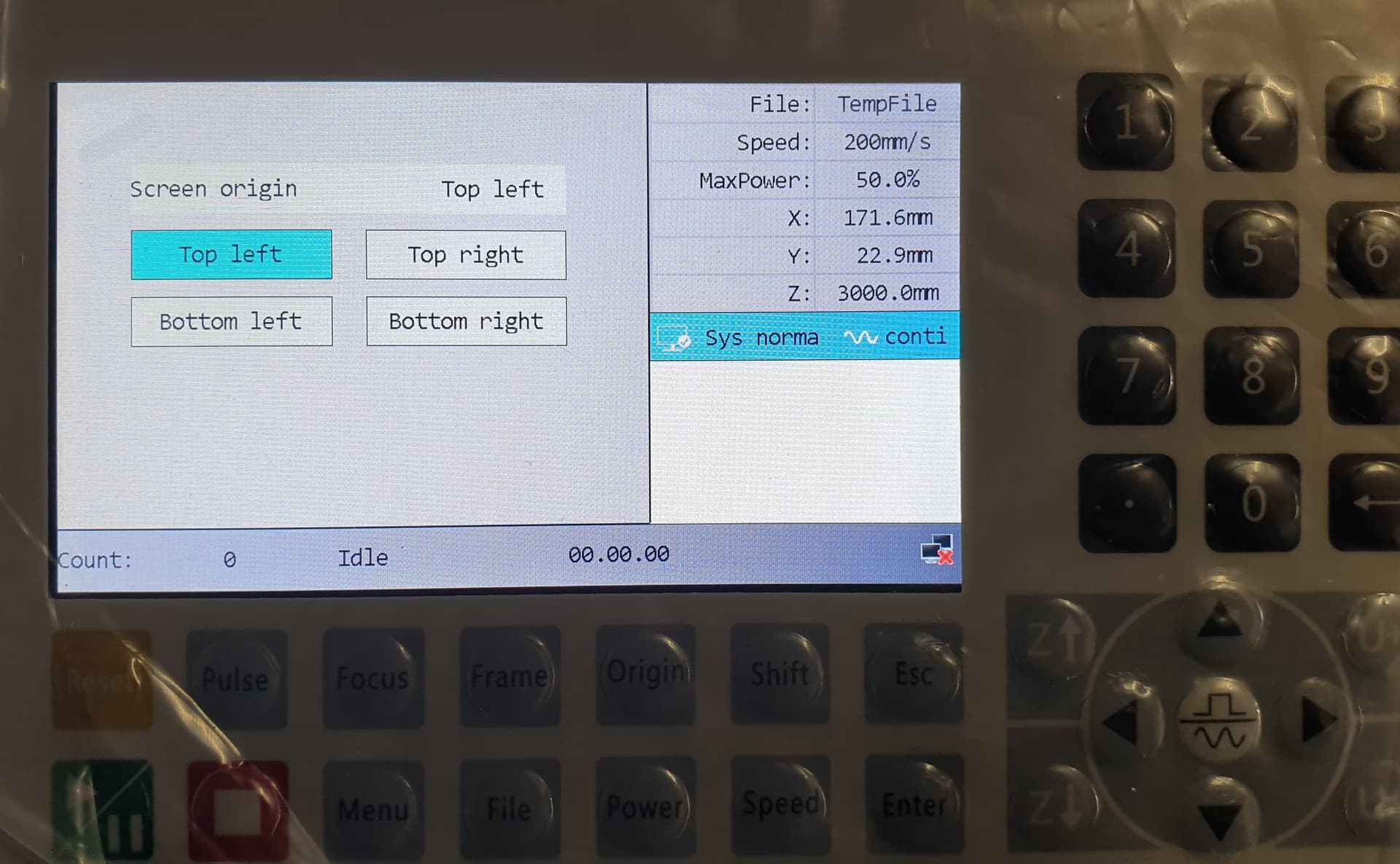
@Cees interesting indeed that your limit switches are the same like mine but the strange things is that from my side i must put “lmt pol” in Negative and you indeed have it in Positive. Because if i put “lmt pol” in positive when i do a reset the axis make a grinding sound and they stay blocked until i push stop. Ther option “Screen Origin” in the picture are related to the screen not to workplan and in any case is the same of mine. Also your limit switches are yes NC in the pictures but are “not” triggered like i see in fact the laser head stay far from Limit switch … The limit triggered that you see are Limit + and not Limit - and normally the Limit - are used for homing. Or you did the wiring configuration using the Limit + ?? May you send me a picture of the front of controller, if it’s possible, just to see the wiring ? Sorry but i would resolve this mystery.
Thanks in advance and for your interest.
Lmt*+ inputs will not work for homing. They are for ‘hard’ limits outside of the workspace.
How do you know they are the same?
Pretty much assures you have different type of limit. Most of them seem to be ‘pull down’ as they are the easiest to configure for mechanical switches…
Not following you here. They must trigger or it wouldn’t home.
![]()
Hi Jack, i know that limit + are not for homing , my reply was for Cees. My “are the same” is related at NC or NO and mine are NC same like Cees.
“Not following you here. They must trigger or it wouldn’t home.”
Yes I know fine but if you see fine the Cees picture the laser head stay distant from home position and then the Limit x - and y -are off but limit x+ and y+ are on … this condition (LimitX+ and LimitY+ red) can happen in two situations:
1 - Cees did a reset but has stopped before the homing was completed
2 - He has 2 limit switch at the end of axis for emergency and are pushed. (But he haven’t them because i saw his configuration).
Hmm… it confused me before and now it confuses me even more.
So my take on the switches: my machine (which looks very similar to yours by the way) has limit switches at the home position (limit -) and not at the end position (limit +). They are NC and with [Lmt Polarity] on ‘Negative’ they appeared red on the FUNCTION+ screen. I guess setting the [Lmt Polarity] to ‘Positive’ is reversing he signal expectation for all the limit positions even the limit + which are not connected. Not connected means ‘open’ which causes the limit + to show as triggered in the screen.
With the opposite settings the homing didnt go well (painfull banging of the head in the corner  )
)
But as Jack mentioned… I guess the limit triggers / homing is not your/ our issue as it is working. However my feel is that it has to do with things being reversed in general: the problem is (at least it was for me) that the motor directions are good, the keying directions are good and the homing works yet the machine thinks it is supposed to be RB after homing which is wrong.
Anyways… I am far from an expert here’(more the opposite) … I guess I just got lucky getting it to work and I am sorry I didnt record my actions properly.

Hi Cees, from my side if i put the lmt pol in negative all goes fine related to homing and i have the NC type of limiter. Due that also you have the limiter type NC i’ wondering why in your side you must use lmt pol in Positive and works and in my side if i put Positive the result is grinding axes… Is related with my problem ? i don’t know but a this point any clues is important. Ah, i forgot… thanks for the wiring picture. I saw it’s the same like mine.
NC is normally closed. If you set the Ruida ‘Limiter Polarity’ to ‘False’ it expects the input to be pulled low when the switch is active (triggered).
If your machine homes properly with this setting, you have NO (normally open) limits.
With it set to ‘True’ it expects the limit input to go high when active.
Is this a reference to Lmt*- and Lmt+ or to the minimum/maximum travel?
I believe, it thinks quadrant II is home, which would mean front/right.
If it ‘thought’ it was in quadrant III, then the Y axes would operate properly.
![]()
@jkwilborn , just to be sure about the limiter NC or NO difference… i took the two wire that coming from the limiter and i misured with my multimeter in Buzzer position and if I put the two tips on the wires the multimeter buzzing while if i push the lever limiter the buzzer stop … for me this is NC or i mistake ?
@Cees Cees please, if you do not mind, may you send me the file vendor and file user that you use ? Also , your driver controller how many steps have you set them 400/800/1600 … and you have also 2 nema 17 for the axes ?. Sorry for many request but it’s look like you have similar machine like mine
Regards
No worries Giuseppe,
It does seem we have a very similar machine. I have added two picture. Mine is a Chinese Goldmark TS4060.

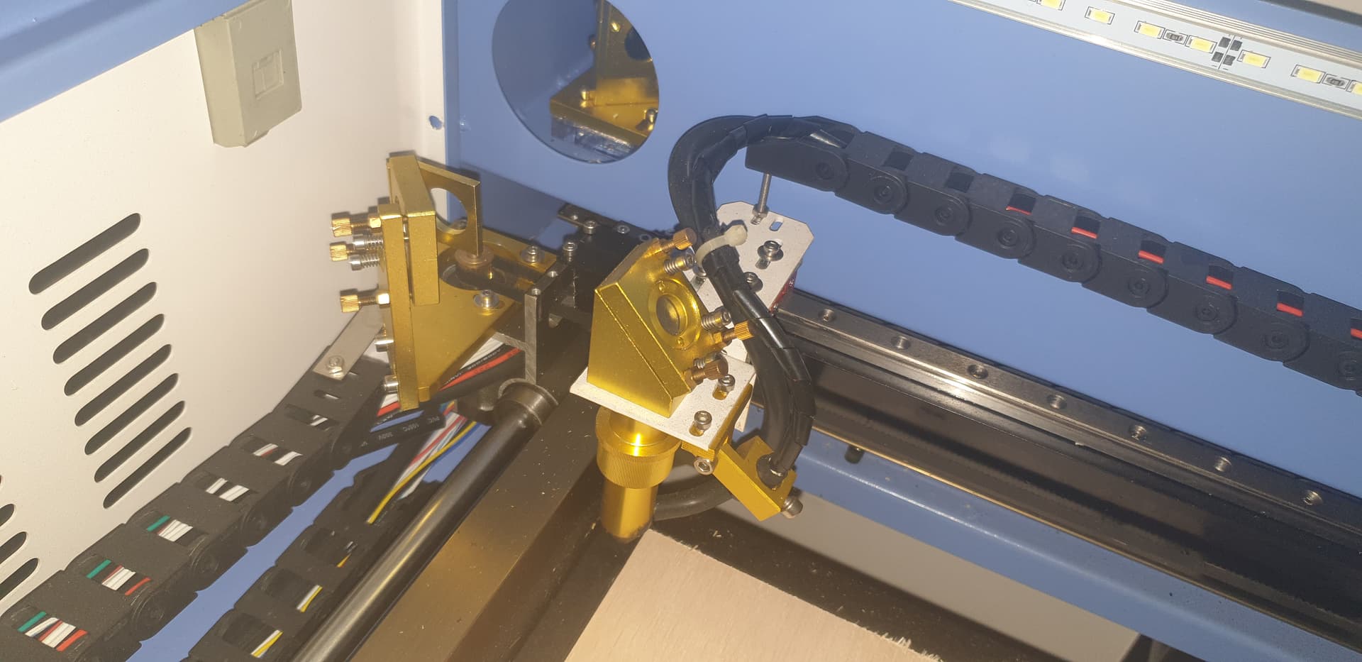
I have included my Machine settings.
Machine Settings.lbset (14.3 KB)
NC or NO: I agree with you if you measure for continuity (buzzer) when the switch is not touched and the buzzer goes then I consider it a NC (normally Closed) switch. As far as I understood, most end stop switches are NC as this is more fail safe than NO.
Let me share with you some more weirdness: So the behavior you are seeing is rather erratic. I couldn’t figure it out either so as a last resort I did a Machine Settings to Default … and after that it was solved.
But I still had a number of other erratic problems (engraving -fill shape- worked, but a line object didn’t work. I used one speed (about 20mm/s) , what ever speed the job was set at and couldn’t even change it manually during the job. The power settings of the job were unpredictable, sometimes no power and sometimes it went to max power…
I had tried every setting and was about to call out for help here on the forum… and then I thought that I hadnt tried going to default user settings… did that, filled in the settings again as I had them before and… everything is now working as normal…
Have you tried going to Machine and User defaults?
@jkwilborn I have measured my limit switches and they are NC. And everything works properly with the limit polarity set to positive…?
Hi Cees, in which way did you machine and user reset?
Then you are confirming that with switch NC you use lmt pol in Positive… this is strange because in my side i must put in Negative if not the axis while i do the reset start to grind… do you have meccanical switches
yes ? BUT … i discovered one thing… that the axes grinding just for 4 second and after start to do the homing but when arrive at the limiter switch don’t stop… bah… from your pictures i didn’t see the limiters …, i ask you again… your drivers controller how many steps have you set them 400/800/1600 … and you have also 2 nema 17 for the axes ? Anyway , I have a sensation that i’m arriving at the solution. I hope…
Thank you very much for your pictures,files and effort
I hope it will help Giuseppe, I was very frustrated about it myself the last days.
I hope this picture will show more of the limit triggers. Does yours look similar?

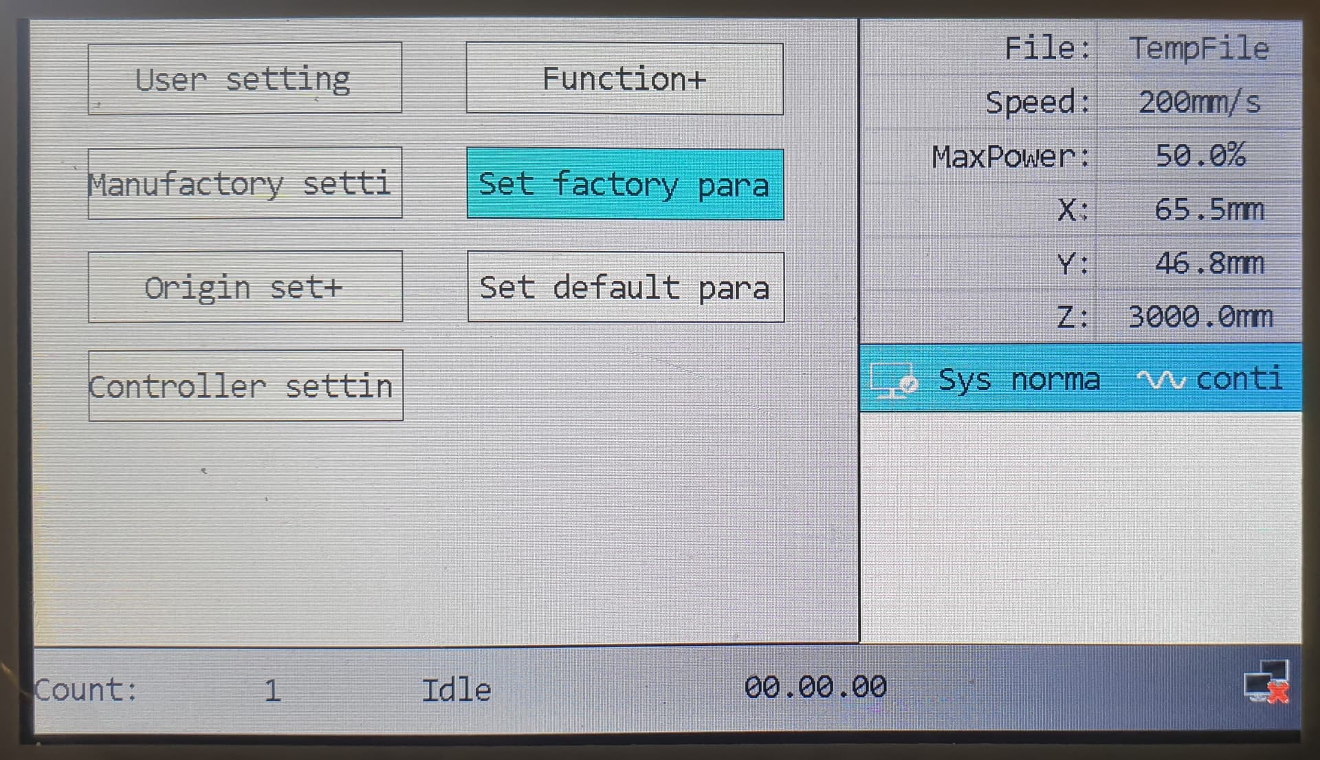
Bellow is the photo of the menu with ‘Set Factory Parameters’ and ‘Set Default Parameters’.
First I did ‘Set Factory Parameters’ and that apparently helped solve the erratic homing and orientation problems. Tonight I did ‘Set Default Parameters’ and that solved my other erratic problems.
Now I am only left with RDWorks not able to connect with the machine. Bot USB and Ethernet are not connecting. Lightburn works fine with USB but is also not able to connect via Ethernet. But that’s for another post Altogether what I thought would be a nice Sunday project has taken almost a full week.
You will get your issues solved as well Giuseppe. Let me know if there is anything further I can help you with.
Hi Cees, tomorrow i will try what you are proposing me … Machine and user defaults and i will see, and yes the limiters are the same. Just another question… when your machine does the homing is very slow ?
For this i asked you which settings you putted in your driver stepper 400/800/1600 etc… and if you have the nema 17 stepper motor for the axes…
Thanks.
Before my problem was solved homing was very slow indeed… crawling and stopped after 10-15cm (maybe timed out). Indeed NEMA17 and my controller was set to 1/32 steps.
I am anxious to hear how it turns out … keeping my fingers crossed
1/32 it’s equal in your steppers drivers with which value? 800/1600/3200/6400 etc…

Hi Cees, also in my side the settings that i putted is 6400 - 1/32… but the homing procedure is very very slow… the steps after tuned are fine … the movements in jogging are fine only in homing are ultra slow
I had that too before I solved the homing problem. The controller behaves erratic. I do believe it has not to do with the settings itself but within the controller reading/interpreting the settings.
If you haven’t already, I suggest you try to reset to defaults as mentioned above and lets see what happens, this solved it largely for me.
One of you set Limit Polarity to true supporting a NC switch, the other has it set false, meaning a NO switch. Make sense?
Neither is ‘safer’ than the other, but the NO are pretty much an industry standard from the 70’s when I worked with them. It has 1/2 the wiring, so in my book, that’s 1/2 the troubles. At least with mechanical switches.
Controllers actively pull up on the inputs, if you use the other logic, you have to actively pull it low. This could be a problem if a peripheral is not powered up. If it’s required to pull it low it has to be operational. The chiller for my machine pulls it low for an operational status, otherwise it’s an fault. Without an active pull down you now have a high impedance circuit that is susceptible to noise. Both work and are functional. Personally I’d prefer a ‘sink’ configuration.
Most micro controllers have internal pull-ups to facilitate ‘wired or’ configurations they are so common.
I think you are just ‘used’ to high levels meaning on, in the end it’s all relative.