Machine: k40 custom (working area 1000x1000 2 nema 23 for y axis 1 nema 23 for x axis 4 nema 17 for z axis)
Board: cohesion3d with external stepper driver tb6600
Firmware: _Smoothie last upgrade
Problem/ Question: losing step/unaligned between cut and engrave
Hi to all I have this issue between fill scanning and line cut when i scanning at 0°(the lines are horizontal) so I had looking for mechanical desalignament, motor break, or the tension of belt but is everithing ok, so my problem probably is eletronic, or firmware parameter.
I have increased the voltage on motor, and I change the microstepping on the external drive but everything is the same.
I have a great improvement if I increase the line interval in the lightburn fill option but the resolution on a photo is very low
I can scan a photo or image perfectly (in vertical) but i need to have also a perfect scanning in horizontal because i need to engrave a vector image and in this situation I have a losing step
so i’m looking for backlash compensation in scanning offset adjoustament but when i try the scan is perfect, there isn’t a difference between the lines
help me please!!! it’s like if the y axis motors can’t make the small and millesimal movement in the same direction (I have 2 nema 23 with 2 external drives for y axis and 1 nema 23 with one external drives for x axis)
thank you all
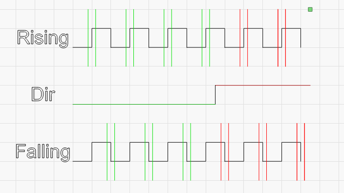
The horizontal scanning issue is not backlash - it’s skew (lines that should look like | look like / instead). That’s likely caused by using the external driver, but not setting the step polarity properly for the external driver. Cohesion3D’s forum or documentation should be able to tell you how to do this.
A step pulse is a transition from low to high, or high to low. The controller will hold the line low, and pulse it high, or hold the line high, and pulse it low. The transition itself is what matters, and motor drivers will either look for a transition from low to high (rising edge) or high to low (falling edge) to accept as a ‘Step’.
If the laser controller believes that the motor driver is looking for the leading edge signal (when it transitions from low to high), it will pulse the line, and could change the direction line immediately after that. If the motor driver is waiting for the falling edge, it will see the direction change BEFORE the falling edge of the pulse, meaning that it will change direction one step too soon.
In the image above, the upper line of steps is interpreted as 4 steps in one direction, then two in the other. The lower line is interpreted as 3 and 3, and the only difference is which side of the step signal the driver is looking for.