Here’s a breakdown of making toning work on DC-excited CO2. Practical experiments show it works very well. What we’re going to do is pervert the system’s grayscale mode by lowering the Ruida’s PWM freq so far down relative to its speed that it’s creating a regular pattern of fixed-spatial-period, continuously-variable-duty dashes that represents much more detail that any dithering method. The goal is to get a proper software solution that isn’t a PWM hack- as crazy as this sounds, it’s not actually more data than existing dithering.
Right now it really needs a potentiometer for current control, since the power PWM gets commandeered to do the dithering instead. Ultimately it would not need to work this way.
There is a fundamental speed limit- it’s not the power, it’s the bandwidth of the tube. An RF-CO2 laser can actually modulate its output at 20KHz. A diode can switch very fast too. Practical experiments on this Reci W6 show it’s about 500Hz. I got the best results at 300Hz.
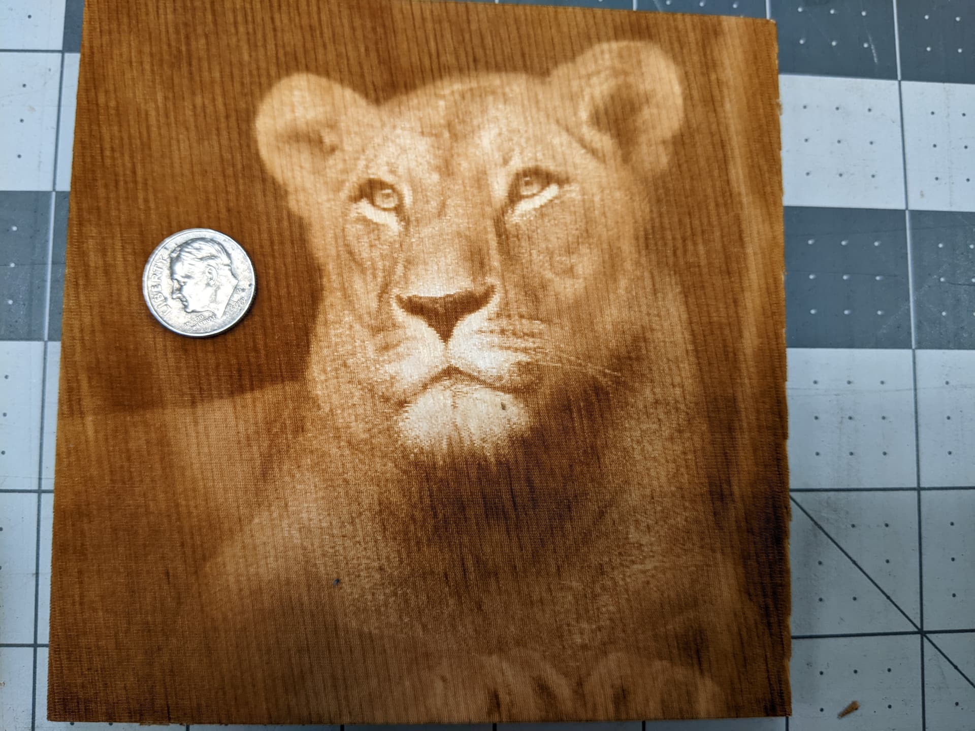
First, we need to determine line interval (LI, same as focal spot size). This machine has a 2.5"FL lens and has a pretty coarse 0.25mm spot, but will still produce amazing image quality. The material must be very flat and well-focused, otherwise the widening spot size will smear this up (like any dithering method)
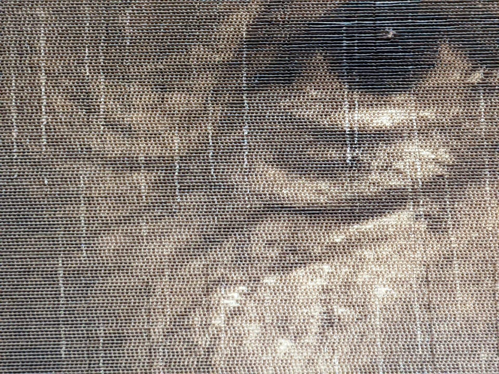
From there, we need a spatial period of dashing about 1.333x the LI. So we’re at 100mm/sec and using 300Hz, resulting in a 0.333mm spatial period. Smaller results in virtually no unburned area once the spot starts to burn, whereas a notably longer period (>1.875x LI) makes visible dashes. Now, the “power” is being modulated at 300Hz, with a spatial period of 0.333mm. The “Power” is NOT controlling the power anymore while the beam is firing. It is critical to understand this part, it’s the core of the principle and perverting the normal laser control mechanisms.
This is where it’s pretty important to have a current potentiometer on the supply to avoid overburning- I turned the W6 tube from the factory 26mA recommendation to 9mA and got really, really good results. Again, adjusting Max/Min Power can’t actually adjust the power- these are controlling duty on the dash.
Two notable effects. As the duty approaches 100%, the dashes merging are coming up less linear.
And on the Reci W6, the beam is slow to start. Now I have 16% Min Power set IN THE RUIDA CONFIG. So I set “max power” (again, not actually the power) at 70% and “min power” on the layer (in addition to the 16% min powerRuida config) at 20%. Below that, light tones don’t fire long enough at 9mA to start the lasing and make a burn, which would create a dead spot at the low end of the response curve.
Does RF respond better? Well hell yeah. Mine’s about 0.20mm LI, and I’m currently capped at 1500mm/s. The beam can modulate actual output at 4KHz no problem, making a 0.375mm spatial period (1.875x the LI) that was working quite well. Downside, no potentiometer to control beam power, so it does tend to overburn.
This is a 240mm x 175mm example done on the Reci W6 machine turned to 9mA with the enclosed project. 300Hz, 16% min power/100% Max in Machine config.
Here’s the thing- trust me- you can use Enhancement, but DO NOT touch the brightness/contrast/gamma UNLESS the original photo has an actual problem in its b/c/g. When the burn parameters are right, it will very literally render any photo as the photo is. If it’s not right yet, then adjust the current potentiometer and min/max power settings for the process, rather than tweaking the photo. The line interval should always be the beam’s spot size (which can shrink when the power is reduced or speed is increased). I don’t have a comprehensive picture of DC-excited tube bandwidths but about 300Hz is probably going to be the case for these and we want to keep this freq as high as the tube will resolve. The speed needs to be =(LI*n*freq), where 1.333<=n<=2.0.
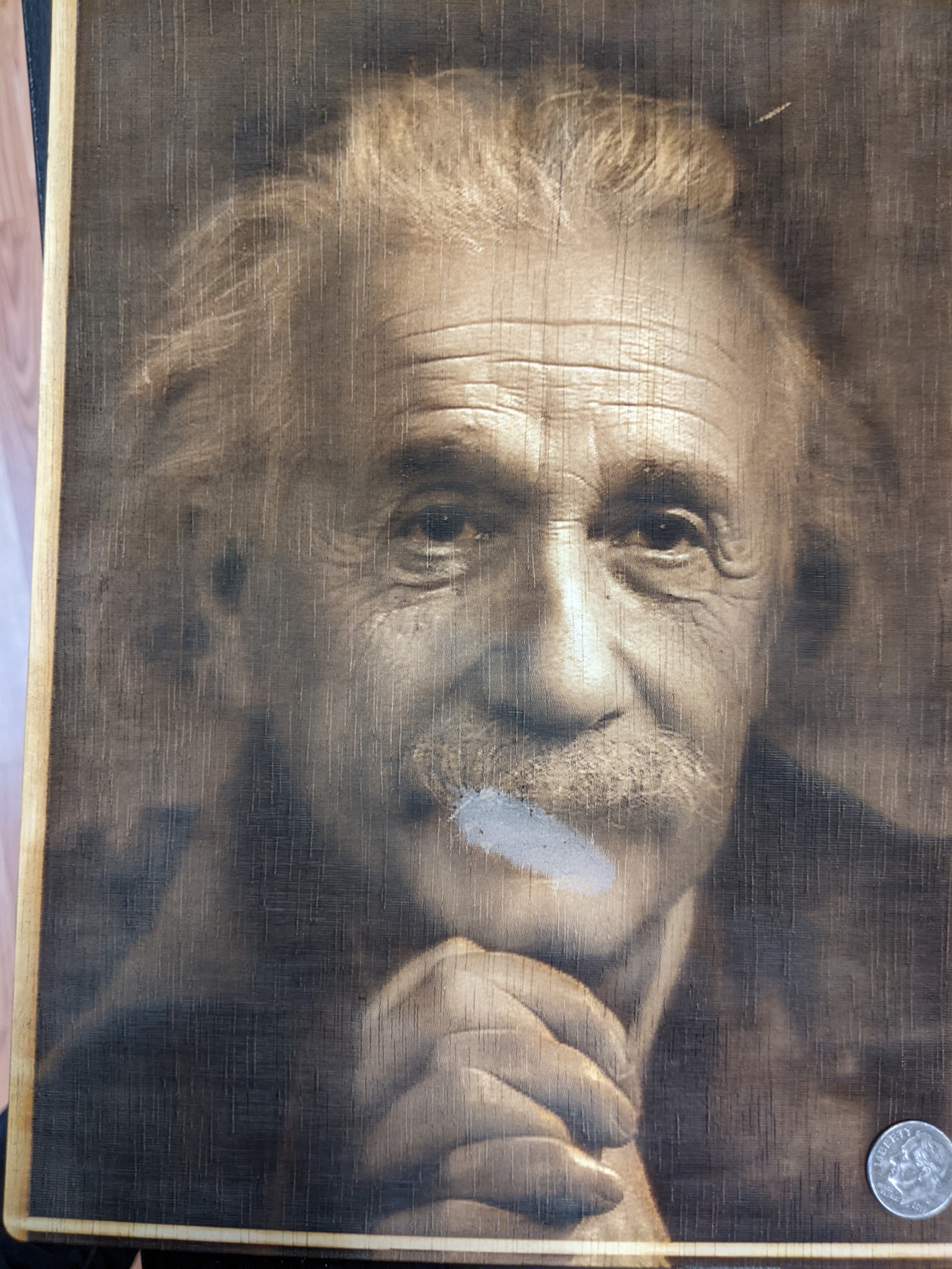

einstein300hz.lbrn2 (994.8 KB)