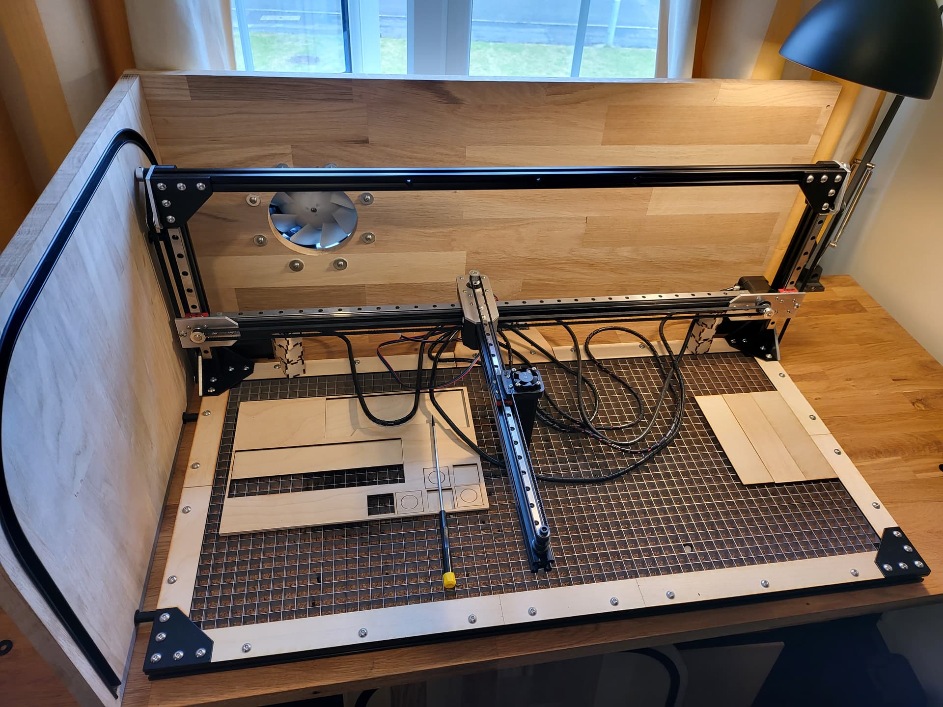
I started experimenting with laser cutting a few years ago with a simple Neje Master device. It proved to be very useful, so since then I’ve been evolving the design into what you see (partially re-assembled) above; a three-axis design that’s been working wonderfully for while now, thanks to the brilliance of Lightburn and GRBL.
However as I’ve upgrade the laser diodes they’ve gotten heavier… and with the latest Neje e40 module fitted, the unsupported y-axis is sagging proportionally to the distance travelled along the axis; up to about 2mm.
I don’t know if this is just an inevitable limitation of this design, or perhaps my linear rails are just not very good and don’t have the tolerances they should.
I’ve thought of a few approaches to fighting this:
Completely re-designing the gantry to replicate the ‘NEJE 3 MAX’ and similar designs (I’d rather not if avoidable)
Using a second (under-slung) linear rail across the x-axis to provide extra rigidity (the geared z-axis steppers can handle the extra weight just fine)
Buying a better quality linear rail for the x-axis (quite long, so expensive)
Modifying GRBL to automatically apply a z-axis offset proportional to the y-axis travel
Using a different GCODE sender with a ‘bed levelling’ feature to achieve the same thing
Before I embark on these potential solutions, I searched for similar scenarios and alternate solutions but came up empty. I was wondering if anyone had run into the same issue and found an elegant solution that doesn’t involve completely changing the gantry design?
Hi
I looked at this problem when building my own laser, not quite the same as yourself, just similar problems.
No matter how you respond to the oroblem youvwill increase weight with any type of stiffener and orvlose travel distance.
The most obvious i see is that the linear slide must be high quality this is the real difference as slop in manufacture will be revealed.
I took the view of placing two high quality linear slides hard up to each other with a corresponding plate made to spread the load. To date this has worked.
Yes you get less travel and you may even have to slow rapids down.
1 upgrade slide
2 spread the load
3 i assume everthing else is tight and square.
4 if you have reached the limits of your machine then the choices are move ahead or stay within designed parameters.
I’d skip this option, doesn’t really ‘buy’ you anything and costs you money.
The issue is the cantilever design along with the fact this is no ‘structural’ rigidity to the design. It has to support the gantry itself plus all the other stuff that goes with it, including the laser module and wiring. This inherently results in some type of harmonic vibration. Add mass to the system and it’s even worse, including sagging of the gantry. As you make the parts with more strength the increasing mass exacerbating the issue. If you look you won’t see ‘large’ machines with type of design. It’s a loosing issue to maintain this configuration.
The only real ‘fix’ it so support the end of the Y axes so it’s not hanging out in space. If you do this, the X axes motor might be find, but you will undoubtedly need to install a driving pulley on the ‘new’ X rail. If you don’t do something to move both ends it will not move smoothly and it will ‘wobble’ as it moves.
The Chinese machines have a shaft running between both Y axes belts driven by a single motor. My Y motor is centered, with a shaft to each side. This prevents torque build up and keeps the gantry parallel.
if your X axes rail is torquing up, this may help. I suspect it’s your Y gantry that is failing you.
The first would have to ‘post’ process the Lightburn generated gcode If you have any issues, you are on your own. Not to mention any change would have to be preprocessed before you could run it. You’d have to leave Lightburn and all the laser controls it has to process the gcode.
A different sender might be a quick solution if you can find one that deals with this and you can interface all the various software/hardware connections. You will still be out of Lightburn…
IMHO, the only real solution is to support the end of the gantry correctly.
Good luck… it is a nice creation, you just grew past the design limits…
Many thanks. I’m very pleased with how it has turned out and performed until now; but as you say, the latest module upgrade seems to have exceeded the cantilever design’s limits.
My hope was a relatively minor change (such as replacing the x-axis linear rail) might bring it back under those limits with the new heavier laser module.
if your X axes rail is torquing up, this may help. I suspect it’s your Y gantry that is failing you.
My current theory is the x-axis rail and block (which bears the weight of the y-axis and laser entirely) has a little play in it, allowing the y-axis to deflect slightly. It seems unlikely to be the z-axis extrusion/rails/blocks twisting or y-axis itself bending - but I could be wrong.
I’ll probably order and fit a Hiwin rail, as it’s a quick swap out and will still be useful in future even if it doesn’t solve the problem.
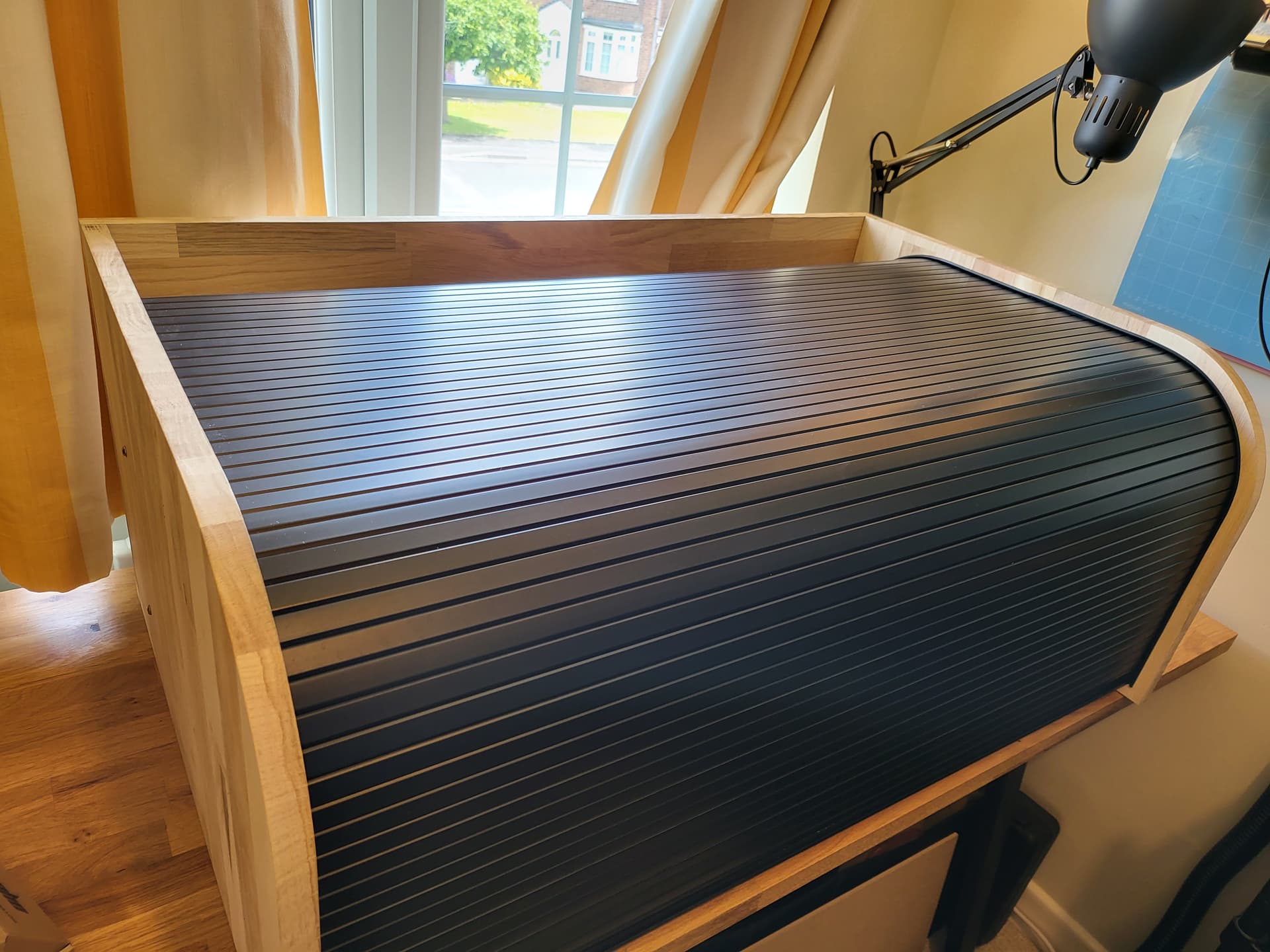
In case you’re interested, it looks pretty neat with the enclosure assembled and door fitted…
The cheapest fix is to shim the legs to slightly raise the frame by the amount of the droop with the laser full out at the end. That will buy you enuff time to save up for a gantry style machine.