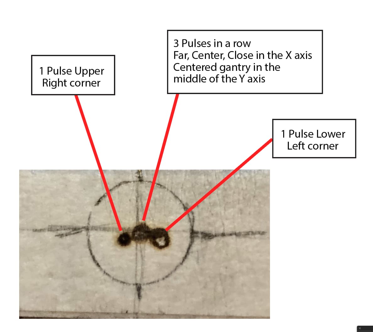
Hello folks. Been trying to get a good cut from this Black/Red since day 1 (6 months). Aligned the machine with all “axis’s of travel” for mirrors 1, 2, & 3. In the attachment the central pulse alignment is aligned right on top each other X-axis. But when I go to the corners they are not in alignment. I have checked tube alignment and every thing I can think of. Suggestions?
hi, take a look at this ![]()
The bed HAS to be completely level. Not level to the ground but to the gantry. Cheaper lasers use less quality steel and lighter gauge, this often causes warping in the travel of the head.
This issue could be caused by so many things it’s hard to be definitive.
Are you sure your mirror 1 to mirror 2 alignment is accurate, pulses coinciding both nearest and furthest positions from mirror 1 like your centre dot in the picture, on top of each other?
For the outer two pulses, how are they close to, and furthest away from mirror 2?
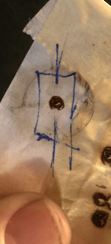
Here is a diagram of the pulse sequence. It aligns perfectly 3 pulses on the X-axis but when I move it to the corners it doesn’t align up. It never has, but I’ve only had it cutting maybe 10hrs in 6 months. I’ve been trying to solve this. (I am disabled and can only work with it a couple of hours a day)Could it be one of the Y-axis belts is not square, or a few chogs off? I can’t find a way to adjust it. I can loosen the tension but there is no adjustment except where the rod is attached to the motor differential. Very frustrated (maybe it isn’t clear the central pulse mark is three scorches and the other 2 misses are pulse 4 and 5. Another forum expressed that my mirror #2 is set to high…what? huh? maybe but that makes no logical sense but have come to decide that with this laser… nothing does make logical sense 
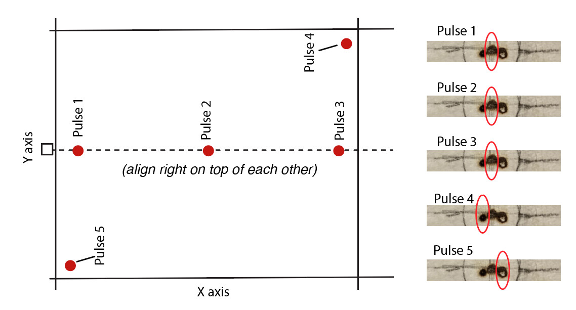
I’m going to say your #1 mirror is not well aligned. #2 mirror is able to steer it back on track, but that only works at one specific distance away from #1. (pulse 1,2,3)
Double checked the Y-axis travel alignment and it’s spot on top of each other just left and down about 1mm from center. thanks for the idea though.
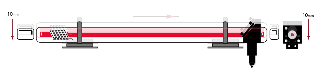
Update: Did a preliminary ruff test by moving mirror 1 down (4mm) from the tall perch it came on (at the very top 3mm of the rod), adjusted the tube accordingly, lowered mirror two with a quick ruff alignment and shockingly it ruffly corrected the issue for the most part. I ran out of time but will proceed to tighten the alignment with the lower overall pathway and axis of travel in both directions. Still scratching my head as to why this seems to have corrected the problem I have been fighting since day 1. Will keep all reading this informed for future knowledge in the forum. Thanks to whomever suggested the problem was most likely due to highth being to tall. I cant find the post where I saw it.
Update Update: Dropping the overall horizontal axis of travel across the mirrors and head 10mm has solved this enigma. Why? not a clue how dropping the plane affected the horizontal movement. All mirrors were set as neutral as possible so mirror angles are not a contributor as the Y and X axis’s of travel are set right on the money without any mirror adjustments and all 4 corners also align. I have followed some of the configurations to the mounts and tube I saw on RDworks. Thanks for the suggestions and hope this helps someone else that may have this issue in the future.
Your beam never launched off the first mirror correctly which can be seen clearly by burn 4 and 5. Probably made up for some of this with mirror 2 which is why burn 1 2 and 3 were good.
If you get close to spot on you will see similar…fine most places but not at say far corners.
Why it improved after moving the tube is simple. You changed the launch angle of the beam into mirror one and without intending to may have improved its subsequent launch off mirror one.
Reflecting a laser beam off of mirrors is like playing the game of pool. Angle in equals angle out accept in pool we bounce the cue ball off the bumpers in a flat plane. The lasers bounces off its mirrors in all 3 axis and so complicated the process.
In more complex laser delivery systems like medical CO2 lasers we spend a lot of time making sure launch angle ism perfect before every going to the delivery mirrors which are the ones that move…for us it is mirrors 2 and 3. In medical CO2 we have 6 of them in an articulating arm…yep 6…its fun to align. If our equivalent of launch off of mirror one is even slightly off…you will never get rid of beam walk. I would spend a lot of time getting this perfect.
It is tougher on our cheap chinese lasers as we do not have a combined red laser beam back at the tube or this whole process would be exponentially easier as we could see the red beam move real time instead of doing burns.
Back on track though when you moved the tube you also changed the angle in and angle out of mirror 1 which showed as an improved or changed result out at I assume mirror 3 burn. Which shows the launch out of mirror 1 was off.
When I check to see if mirror 1 is spot on I want to have the beam travel as far as possible so I tape a large craft stick over mirror 3…yes 3. I then run X to its max position away. Now i will move Y to 0 which is close to mirror 1…do a burn. Then run Y to its limit and do another burn and check it. Since I did not move X then mirror 2 is not affecting beam coincidence…IE burning in the same spot. Even if 2 is off it will only affect where it burned but if X never moves then it should burn in same spot.
I do it this way as the final check for mirror one as it gives me the farthest travel of the beam to spot movement.
Just taping the burn stick in front of mirror 2 only gives me a 1/3 of the beam travel I can get by using mirror 3 and X at max distance.
In preliminary mirror 1 adjustment then yes I tape burn stick over mirror 2 thats just to get it close first.
SO here mirror one is the launch mirror and everything needs to be perfect or it just gets worse as distance in x or Y is increased
I agree. BUT I have to preface this with I have Parkinson’s and didn’t know the amount of detail needed to align these are when I started this endeavor. As a Illustrator for 35 years I figured it would be a way to create my art with some control between the computer, laser, and composition with tabs and such. That being said I have gone to great lengths to simplify the mirror alignment by re-tooling the mirror stands and stabilizing them to make alignment easier with shaky, stiff, and hard to control hands. I have based all my calculations on the overall height when I got the machine. I had this issue arise after alignment correctly being made from the Tube to the Head. The side pulses off center in the corners has been something I have fought since day one. Once I presented the issue, someone mentioned mirror height and so I figured “what the H—” and tried lowering the over-all plan-ale height by 10mm from Tube to Head. Zoinks if it didn’t resolve the issue. That’s my confusion. Vertical reduction equals horizontal alignment only in the corners. Mirrors are all set to a neutral position as Axis of travel is spot on from painstaking base configurations for easier alignment in my situation (basically blocks with mounted mirrors). Long story but may help someone at least see an unusual result.
I have a similar problem, and am really battling to figure it out.
Setup:
Back left - fixed mirror - M1
Left gantry mirror - M2
Head mirror - HM
So, checking M1:
M1 in position Back left. pulse, makes a nice dot in the middle of my target.
M1 front left, pulse, perfectly on first dot.
Checking HM:
HM back left, pulse, makes a nice dot in the middle of my target.
HM back right, makes a nice dot on top of the first dot.
HM front left, pulse, dot on centre of target.
HM fromt right, dot 3mm above first dot.
Running the head from back to front and doing pulses I can see the dot getting progressively higher. I thought the rails weren’t parallel, but I’ve checked that and they seem parallel in all planes.
So If I’m understanding this correctly, M1 needs to be vertically at 90deg to the Y rails before I can get the rest of the settings correct, and this may involve adjusting the height of the tube to manage that?
The simple answer is the head was 1/2" to high and all the in-between mirrors had to be adjusted vertically to correspond with the axis of travel [mirror 2 came down like 3/8 and mirror 1 came down 1/4 and better aligned with the tube. Why that solved it I have no idea. Somebody with better engineering and math skills can explain. why I guess]. I did have to make a new bracket for mirror 3 (head) to be able to vertically adjust it. I got the idea from Russ and laser lab on YouTube, I’ll. try and find a link and post an image of my banjo machining (don’t laugh). I will also admit to the right hand belt being 2 chogs off but correcting that did not help this issue as you describe.
Very interesting discussion.
In this context, I would like to ask what influence does the mirror in the tube have (the one at the exit, of course)? The larger and more expensive tubes have fine-tuning options at the output optics of the tube that most of our tubes do not have. I have seen a film from a factory where an employee very quickly and more or less precisely adjusts this optics. How “our” tubes are adjusted during gluing of the semi-transparent mirror, it will be interesting to know.
At the relatively short distance from the tube to mirror 1, it is very difficult to measure or judge whether the laser beam angle is 100% parallel to the rest of the frame, even if it hits the spot. At my new machine, I found that a few millimeters were missing in the height of the rear tube holder. I could see that the mirror 1`s frame was very unevenly set up, at an angle of almost 5 degree vertical !, it gave me the suspicion that either the frame or the tube was not level adjusted correctly.
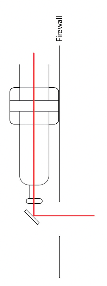
I later to dial it in to resolve this issue further I remembered I had introduced a 3/8inch space between the firewall and the tube mount to accommodate a beam combiner I bought.

After removing it the final tweak has made the alignment is right on.
Not shockingly to my non-engineering mind this doesn’t make sense.
Net Net, although a simple mind as mine, assumed that the beam was the beam and as long as the alignment was square and the axis of travel was ensured that things would work great. BUT, somehow the geometry establish by Omtech has to be followed. Why? Dunno’. ::