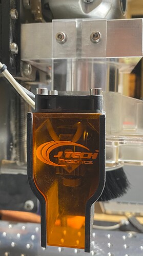
I have used my JTech 4.2W laser happily for a couple of years. I like its performance and it ease of use when mated with LightBurn. The JTech hardware includes a 3D printed magnetic laser mount and shroud that does work well enough. The basic mount slips over the front of the Shapeoko router mount. I don’t know which of the Shapeoko CNC machine series uses that particular router mount (mine is an SO3) but the quick release of the laser head has been really useful… permitting easy changing from milling to laser work for the same project.
Lately, I have found the magnetic mount for the laser a bit cumbersome. It was mounted on the front of my milling mount and it gave rise to a problem. My vacuum tube and dust boot were turned to the left because I did not want to impede the machine on the right where two of the proximity sensors were located. Additionally, I lost about 50mm of working envelope at the front because of the position of the JTech bracket. I also lost a similar amount from my work envelope on the left hand side of the machine because of the dust boot and vacuum tube protrusion.
I thought I would try to solve the issue of getting more left hand side working space by changing the JTech bracket for one of my own design. I still wanted the quick release feature which was most useful. I thought that a single leaf on the left hand side of the router mount would be one way to gain space because it would mean I could turn my dust boot forwards.
I examined the JTech magnetic mount and copied the dimensions and poisition for the holes and magnets. I decided on 10mm acrylic as the mount because I could undercut it by 4mm so I would have and additional bearing surface. I drilled and tapped the Shapeoko 65mm Makita trim router mount. I decided upon M4 cap-heads with a captive washer and spring. Each of the holes was tapped to a depth of 12mm.
For magnets, I purchased 8 x 2mm and helically bored 8mm holes 8mm deep in the acrylic. I would them press fit the magnets into the holes and their proximity to the existing magnets in the JTech shroud would allow a strong magnetic link. I drill two 3mm locating holes so that the laser shroud and head would always be vertical. The 4mm holes for tapping M4 were drilled at 4mm for clearance into the acrylic and 3.2mm for tapping into the aluminium Makita mount. I placed the holes at 25mm centres and at a height of 14mm (the mount is 28mm thick) to avoid hitting the long front to back screws that pull the clamping surfaces together to hold the router.
To aid understanding, I have provided a few pix.
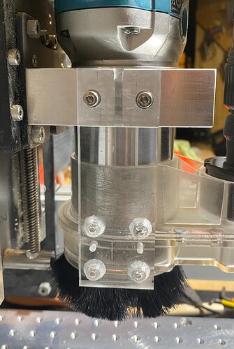
This front view shows the laser shroud held onto the acrylic bracket just by magnetism and using the two locating pins. The two M4 capheads with captive washers and springs are shown attached to the Makita mount.
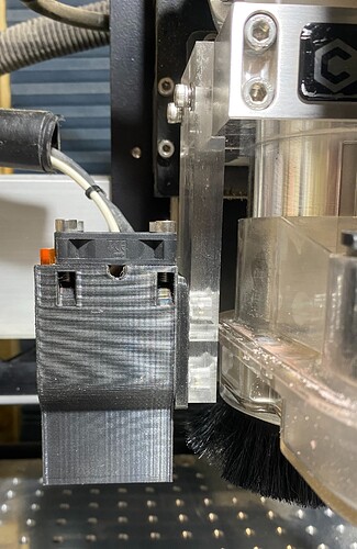
This side view shows the JTech shroud attached with the magnets and locating pins. The acrylic is 10mm thick and the depth of the mount (28mm) has been undercut by 4mm so that there are two bearing surfaces for the acrylic bracket and the undercut helps to locate the 40mm wide acrylic bracket easily. The acrylic bracket can be seen following the perpendicular lines of the router mount.
This is the front view of the acrylic mount. As well as the M4 cap head screws, you can see the 3mm locating holes for the pins exiting the JTech shroud through the magnetic area. The 4 8mm holes are for the 8 x 2mm magnets. Each hole was drilled because the magnets are a close interference fit. The holes are bored to a depth of 8mm to permit close proximity to the magnets in the JTech shroud.
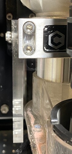
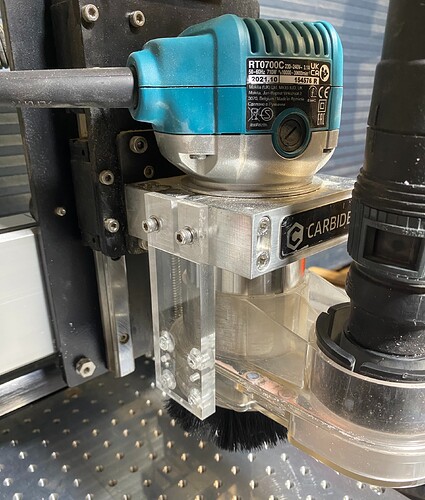
This side view shows the accurate fit of the new bracket. The 4mm undercut in the acrylic is plain to see, next to the router mount
The next image is taken from an oblique perspective to help you locate how the bracket sits in space. This 10mm thick acrylic is the only obstruction to my left hand work envelope now and I am pleased to have gained another 50mm of working envelope.
