Breaks in lines

Hallow
Im new user of Lightburn and i work on eleksmaker 2.5
Im still learning but i have some problems and really completly no idea what i do wrong.
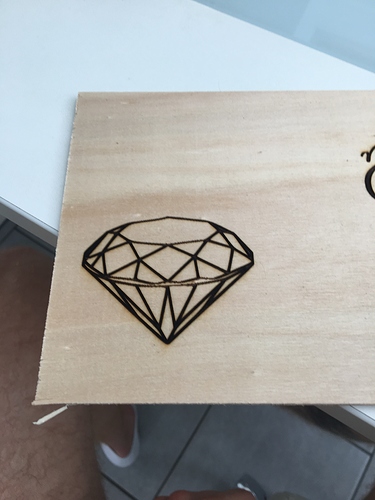
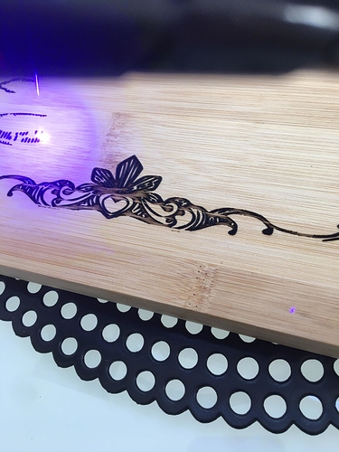
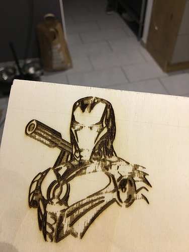
On picture or text that i graver i have breaks in lines (shouldn’t be).
I dont know if its foult of threshold when i trace picture (im still dont understand it- treshold, and i still dont know how to set it fine).
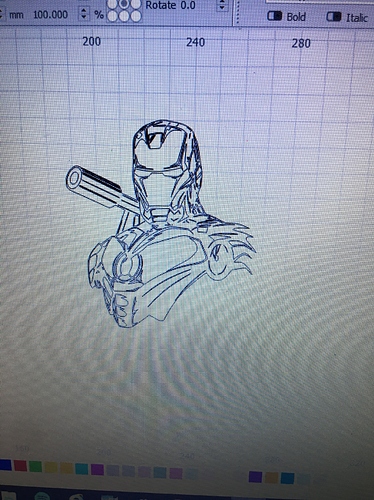
I add some test picture for review

Thank You for help!!

Hi Simon, we will need a bit more information to be helpful. What version of firmware are you using to drive your setup? What cut settings did you use for this job? You mention “threshold”, which is a setting for images. Is this how you have this job set? Is this text created using the font tools within LightBurn or is it an image that you traced? What does this look like in the ‘Preview’ window?

Please provide as much as you can to help us help you. :slight_smile:

speed 1000/mm/m power 100% and 71 minutes works, size is 70mm/50mm

i dont like brakes in lines in middle

how i can reduce time? 71 minutes for that simple projects its long time i guess

Yes, 71 mins is a long time.

You did not answer all the questions and they are important to help you find a resolution.

If you are using ‘Fill’ or if this is an image, changing the ‘Line Interval’ to something with a wider gap between each line drawn to fill the shape. This will reduce the total job time. You can see the effect, visually and time savings, displayed in the ‘Preview’ window before running the job.

speed 1200mm/m
power 100%
laser 2.5 diode
GRBL 1.1e or earlier

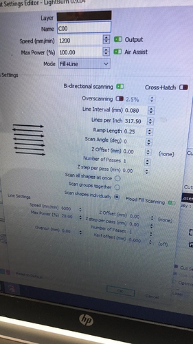
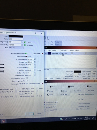
I see from your ‘Cuts’ settings that you have ‘Ramp Length’ set to 0.25. This is used for making rubber stamps where you need to support the “shoulders” of the shape. From the pictures shared, I don’t think you are trying to make a stamp, so turn that off by changing that value to 0.0.

I also see that you have ‘Flood Fill Scanning’ set ON (green). This option is used to scan fill shapes with a lot of open space like a picture frame. Using this speeds the process for slower-moving systems like the Eleks. Turn that OFF (red) as this is not the type of work you are testing right now.

We are trying to help but need the information requested to be of help to you. What device profile have you selected when setting up in LightBurn? And what are your firmware settings? You can type $$ in the LightBurn console, then post the output here so we can review.

$$

$0=10 (step pulse, usec)

$1=25 (step idle delay, msec)

$2=0 (step port invert mask:00000000)

$3=3 (dir port invert mask:00000011)

$4=0 (step enable invert, bool)

$5=0 (limit pins invert, bool)

$6=0 (probe pin invert, bool)

$10=3 (status report mask:00000011)

$11=0.010 (junction deviation, mm)

$12=0.002 (arc tolerance, mm)

$13=0 (report inches, bool)

$20=0 (soft limits, bool)

$21=0 (hard limits, bool)

$22=0 (homing cycle, bool)

$23=0 (homing dir invert mask:00000000)

$24=25.000 (homing feed, mm/min)

$25=500.000 (homing seek, mm/min)

$26=250 (homing debounce, msec)

$27=1.000 (homing pull-off, mm)

$100=80.000 (x, step/mm)

$101=80.000 (y, step/mm)

$102=400.000 (z, step/mm)

$110=5000.000 (x max rate, mm/min)

$111=5000.000 (y max rate, mm/min)

$112=5000.000 (z max rate, mm/min)

$120=200.000 (x accel, mm/sec^2)

$121=200.000 (y accel, mm/sec^2)

$122=200.000 (z accel, mm/sec^2)

$130=5000.000 (x max travel, mm)

$131=5000.000 (y max travel, mm)

$132=5000.000 (z max travel, mm)

ok

Thank you so much for helping
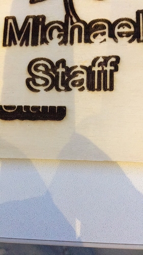
With complex designs, flood fill will skip sections and then go back later to fill them in. If your machine is not very well tuned, this can cause gaps due to backlash, so I don’t recommend using that setting for the design you’ve shown. You’re also engraving on bamboo, and that material has quite varied density, so any lines in the direction of the grain could also (possibly) be caused by the material itself.

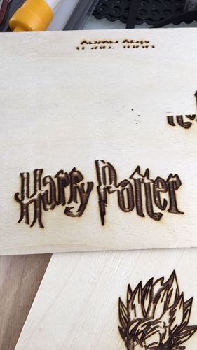
yeah but i have also same at different kinds of woods!
photo for example


and what u mean my machine is not very well tuned. You mean tight of belts?

Not quite - I mean it has to be very well tuned for flood-fill to work well with a complex design. I can see you’re also not using overscan, which is why all the edges of those designs are darker - turning off flood fill and enabling overscan will help both of those things, and with the files you’re using, it will likely end up being faster, because it will spend more time at the desired speed, and less time changing direction.

Flood fill is most useful for shapes like this:
image
In the above image, most of it is empty space, and really far apart, so flood fill saves time there. In nearly any other case, scanning back and forth across the design takes less time than doing all the tiny little back and forth moves you get from flood fill.

okay, i will try tommorow engrave something with Flood Fill OFF and ON Overscaning and Ramp Lenght with value 0.0 then i post here if its better
Thank you for help

@edit
My cmd settings what I paste here before is okay?

Yes, what you posted above is all we need for now. Try the changes I suggested and you should see a fairly significant improvement. Let us know how it goes.

Why its looks like that??

Check the ‘S-Value Max’ setting in the Device Settings window. It should be 255 for your system. I would also turn off the “Fill + Line” mode, and just use Fill for this artwork, and set the ramp length to zero as Rick mentioned. That could cause strange results.

yes, I have s value max 255.
So I understand if I make more complicated project like this above then i need to use flood fill right? Ramp lenght was and it still zero

original picture should be engraver like here

No, turn flood fill off for complicated things. You should really only use it for things with a lot of empty space in the middle, like engraving around a picture frame.

What GRBL firmware is your Eleksmaker using? If it’s very old (like, 0.8 or older) I would recommend updating it. 0.9 works, but it’s not great. Things improve when you get to 1.1f, because it has laser mode, and doesn’t pause for power level changes.

If you don’t have air assist, it’s possible that while doing the outline around the image that the smoke stained the wood causing those streaks. It’s hard to tell from looking at a single image at the end if that is what happened though - it would be easier if there were pictures from a few points along the way from start to finish.

i’ve got grbl m3 1.1e or earlier
Just contour maschine did very well.
i think this “bleeding” is only on the point where should be completly black. how comes?

I suggest you try to produce a simple shape like a circle or square set to fill to diagnose and tune your system first. This will ensure that your hardware and firmware are set correctly and allowing you to get expected results consistently on a given material. Once you have that working properly and in a known good state, you can then move on to a more complex shape and should get the same good results.

This topic was automatically closed 30 days after the last reply. New replies are no longer allowed.