Hi all, Gary O… I have a comgrow z1 10w laser. I have designed a coin to be burned on both sides and cut out! All works great EXCEPT I cannot get the burns to align! (See pictures)
I made the change to use user origin and centered the coins inside the 12” square! I made one coin and used the row and columns to duplicate and then center inside the square!
I used strong magnets to ensure I flipped the board to the correct spot and then did an outline test which matched front and back! But every burn the back is off from the front!
Looking for help! I am making this for a church function and need over 50 coins otherwise I would just burn one at a time! They are small, 1.25 each!
Either something is not perfectly aligned from front to back in your artwork or you bumped the laser head while filpping the wood or your machine moved relative to the work surface or … any of a number of possibilities.
If you upload the file I will verify that everything there is aligned perfectly.
It would not let me add the file… it was too big! so I added a second coin that I set up exactly the same with the same results. Just a bit off center from on the backside.
When you make your array, engrave and cut out the front of your medals and turn them over - without moving your template, you only need to swap the contents in LightBurn (template) of your coin and start. This is how I make larger series and have had no problems with it.
The method I use for front/back alignment (which I’ve found always works) is as follows:
Make you Lightburn file with the two sides on different layers which you switch on and off to send the two sides. This ensures the items really are aligned in the file. Make sure you are using absolute co-ordinates in Lightburn.
Tape a piece of cardboard (larger than the work pieces you are going to use) to your laser bed. Carefully measure all your workpieces to make sure they really are all the same size (even 1 mm difference will affect registration). Draw a box in Lightburn that is the actual size of your workpiece on another layer in your design file. Use this to cut a rectangle into the cardboard the size of your workpiece using the laser. Remove the cut rectangle leaving a neat jig taped to the laser bed.
Place a workpiece into the jig - making sure it lines up properly to the top left corner. Tape it into place at the corners.
Send the first side of the design (engraving only) to the laser
Carefully remove the tape from the workpiece and turn it over (right to left), reposition it in the jig, making sure it fits properly into the top left corner.
You can miss this stage out if you want - but I then carefully slip little spacer pieces under the corner so the workpiece to lift it up slightly from the bed to keep the reverse sides clean. Then tape down the workpiece again.
Send the second side engraving to the laser.
Sent the cut to the laser.
Remove your finished work from the laser - and if you have been careful aligning the workpieces in the jig, your registration should be perfect.
That’s a quite easy task. I described the process here (section mass production):
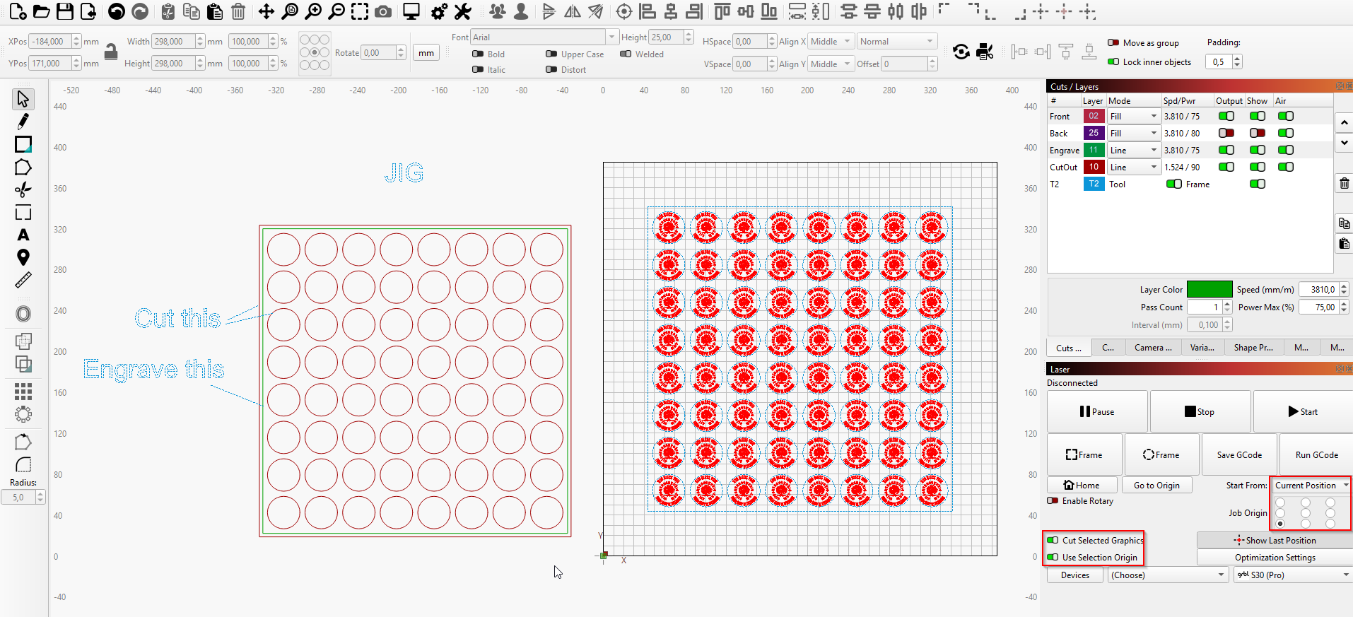
You just need to engrave a square around the holes in your template, which you can use to reference the laser position afterward. Use “current position”, “cut selected graphics only” and “use selection origin” as settings in laser window. Put the square on a tool layer which is also set to “frame”. Then you can frame until you placed the jig perfectly in the workspace (doesn’t matter where) and fire up the laser.
I got interested in this and checked out the LB file. I went through and made some changes that I would apply if I had this project. I did not change any power or speed settings, but I did manage to cut the project time a lot. The Notes explains the project flow.
I hope I did not overstep my bounds here, but I could not resist trying to help.
Hi Bernd!
That’s exactly what I did! I tried from lower left, absolute coordinated and center, user coordinates. Burned one side, flipped and burned the other!
My last burn, it worked correctly on the lower burns but the uppers were off (test piece picture).
I made completely sure I did not hit the laser and did a test to make sure the workpiece was in the exact position. I also use a square on my bed to make sure my workpieces don’t change location!
Pretty stumped with this alignment thing as it seemed pretty easy to set up!
This procedure sounds like what I used exactly! I show two pictures for the coin but they are separate layers that I just turn on and off when checking before a burn
Sorry, but I cannot actually run anything. I am about 1000 miles (NY) from home (FL) for another couple of weeks.
Compare the run times between your file and mine. You will see a big difference. When you have a 5w or 10w laser, optimizing (fiddling with the settings) and checking it with Preview can really help. I consider Preview as probably the single most important tool in Lightburn.
I saw nothing in your images that would indicate this. Just pay particular attention to focusing.
Here is how I’d do it. First, cut the jig. The jig then has all the cutouts and an engraved square around them.
The next step is to select all engravings AND the square (on tool layer) around them. Set the options as depicted in the laser window. Then move the laser head to the lower left corner of the engraved square on your jig. Do a frame to check if the laser travels along the formerly engraved path. If so, start the job. Otherwise, reposition the head or the jig. You can even move the jig while the laser is travelling; this will save some time.
My version was based on using a 12"^2 sheet of 3mm Baltic ply to make the actual coins. Then using the scrap with the holes as the fixture for engraving the back.
…I don’t quite understand that.
When you draw a shape and place it in a specific place using absolute coordinates and e.g. center position, it will always be engraved/cut at exactly the same position, as long as you don’t change these parameters. This is precisely the advantage absolute coordinates provide.
For templates that need to be reversible, however, it must be ensured that the items are symmetrically placed and the center is the same for both sides in relation to each other.
yes… agreed
and that is why I am so mystified as to why the back is slightly off. I didn’t pay thousands for my laser, so maybe it is a flaw in the laser. I am racking my brain as to how it could be operator error, which I can accept, if I figure it out.
Are you saying you won’t accept it if you can’t figure it out?
Seriously, That 2mm error is not much and can easily be produced if you do not have everything glued down. A combination of eyes confirmed you did the Lightburn part right. That eliminates the Seat to Keyboard Interface Error.
I say move the frame or base back into alignment so you can use your grid lines and go on.