Mesmerizing and hypnotic aren’t they…
![]()
Mesmerizing and hypnotic aren’t they…
![]()
Very. I got the machine running at 8000mm/min comfortably. Any faster and the system got LOUD. It did fine at 8000 but I could see where it was missing it’s mark in numerous places under the scope; either before or after where it was suppose to fire. Really no big deal, but there’s no reason why I need to run the machine this fast. I dialed the power down to 20% and the quality was so much better.
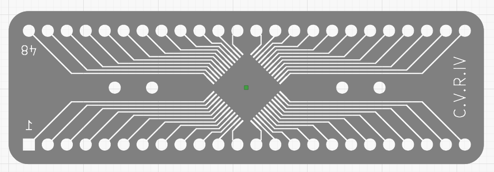
Nice! That looks really cool.
Not sure exactly what your SVG looks like but if you add an outline around the whole area it should essentially invert the areas that are burned. It all needs to be on the same layer for this to work.
The SVG is just outlines. Trying to figureout how much to do in Flatcam vs Lightburn. In a few days im gonna really sit down with it and get this done. Just to busy right now. I cant wait to do this lol.
Are these vector cuts?
Might make a difference on the ‘smoke’…
We would all like to see the svg file you have to deal with. I use flatcam (Linux) and make my own pcb’s as do others.
I just hang a “.txt” on whatever it is and drop it on the reply window… whatever.pdf → whatever.pdf.txt
![]()
Enjoy.
EDIT: I changed the names to .txt but something weird is happening.


Here’s a revision. Notes about what I did.
PCB.lbrn2 (261.8 KB)
Is there a reason why the #1 is mirrored?
Awesome. I will try that. I didnt even notice the mirrored 1. Thats a Flatcam mistake. I wonder why there were two outerlines. Omg i cant wait to sit down and give this a go. Im so excited.
What speeds do you usually laser off the paint on your clad?
Probably a part of the conversion process… It may have converted a line with a certain stroke width into a filled set of shapes to form the wider “line”. This would be the common way of handling a stroke to path operation in an illustration program.
I’ve never done this so will rely on @jkwilborn on this point.