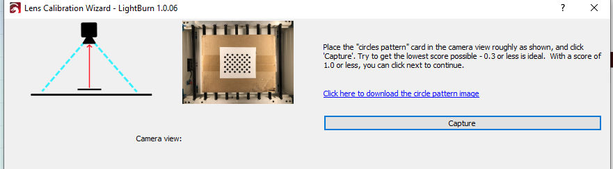
I am using a Logitech C920 Camera. I am lost how to calibrate and align the camera over the moving print area? I can calibrate it with the Y axis pushed to 140mm with the camera mounted on the Top bar (Ender 3 Pro) but I can’t align it. What is the best setup for using a Camera on a Ender or CR-10 Setup?
Have you gone through the initial process of setting up and calibrating the camera already? If not, then check out these links as they go through this in depth. Circle back if you’re having a specific issue that’s unrelated to this.
Using a Camera - LightBurn Software Documentation
LightBurn Camera - Setup and Calibration - LightBurn Software - LightBurn Software Forum
Tips for calibrating / aligning the camera - FAQ - LightBurn Software Forum
I setup the Camera using the pattern. I had to move the bed forward and mount the camera out over the build plate moved 140mm on the Y axis. I was unable to perform Camera Alignment because the X axis bar is in the way over the pattern when homed 0,0, 55 (Default homing for my laser)
Is your question specifically about where/how to mount the camera?
Hopefully someone with your exact setup can pitch in but in the meantime can you send a photo of your current setup and how the camera is being blocked?
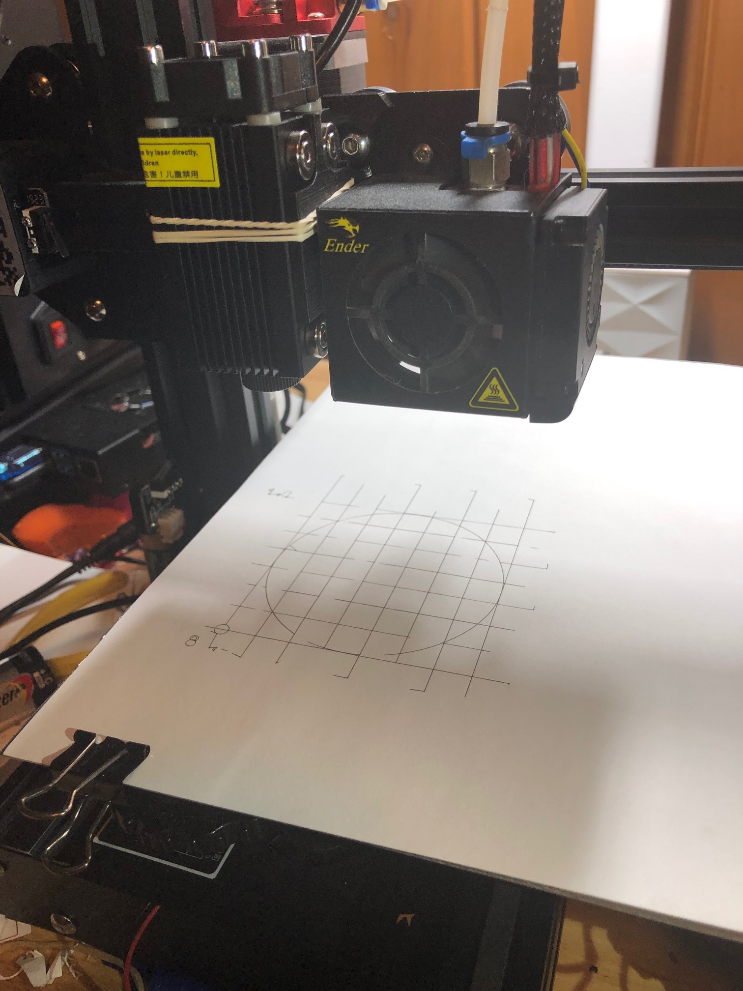
Here are some pictures of my set up and the screenshots from Lightburn. Alternatively, I have created a grid for aligning things which can be seen on the bed.
My questions is how do you mount a camera on a standard Bowden Drive 3D-Printer Setup? I can’t setup the camera to go at an angle like in the tutorial. Only overhead. And the X-Axis bar is in the way of the camera. See pictures.
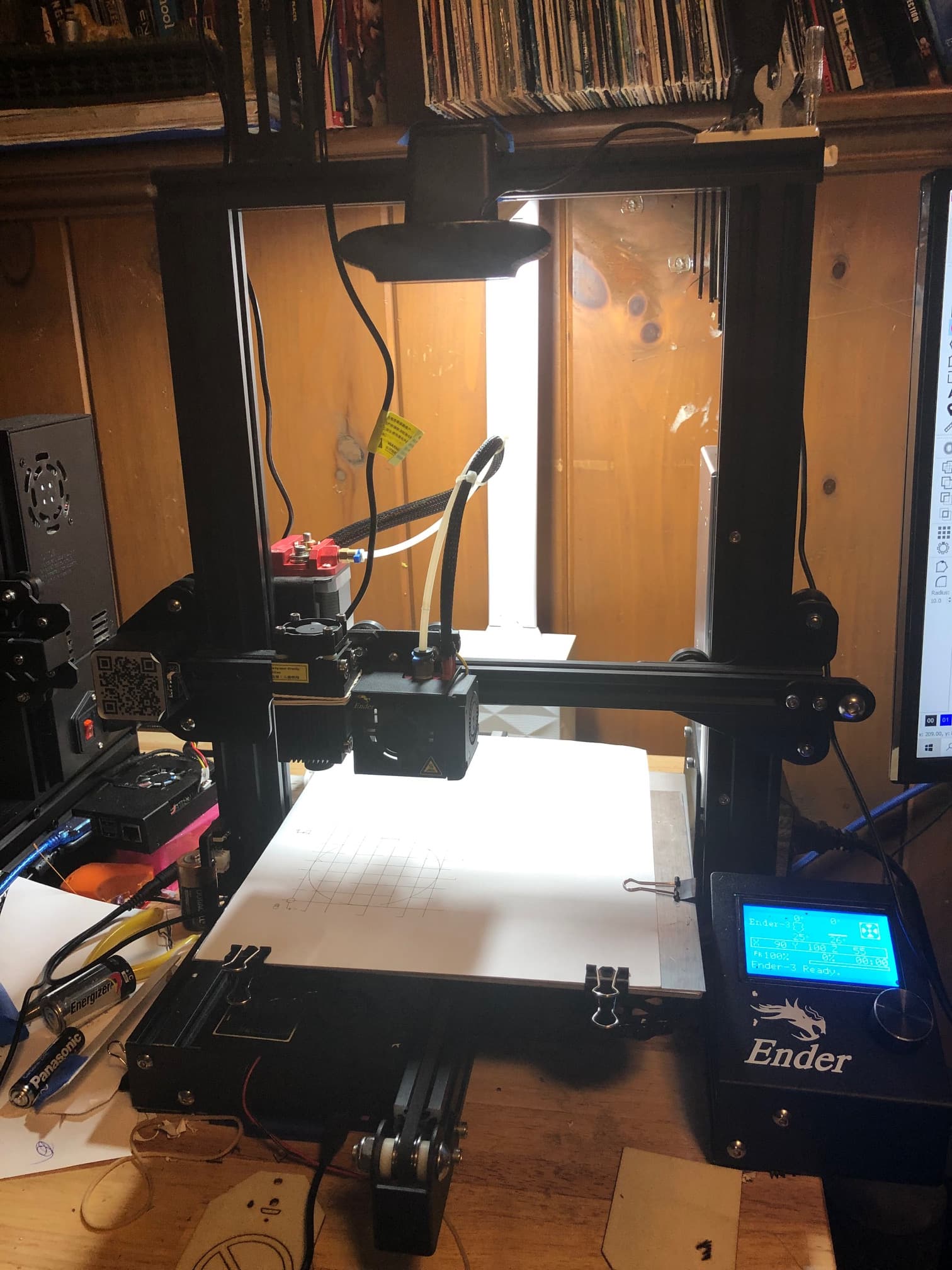

In the screenshot I have moved the Bed 140mm to allow the camera to see the Pattern. But that would not be the normal position for engraving/cutting.
The process of setting up a camera has 2 distinct stages: camera calibration and camera alignment.
Camera calibration uses the pattern and its purpose is to correct for lens and perspective distortion. You do not need to have the camera mounted to the frame when you do this step. So, either temporarily aim the camera to an easier angle to accommodate this step or take it off the frame.
Camera alignment does require the camera to be mounted. It’s hard to tell from your exact setup but it looks like you should be able to move things around for you to accomplish this. You could even push the bed all the way forward to make as much of the bed visible if required.
When I got into the Camera Calibration I only get an option for 90 degrees.
How do I select other angles like in the tutorial. (LightBurn Camera Setup - YouTube)
Calibration has multiple steps where you will be capturing the pattern card from multiple positions.
The diagram of the 90 degrees is relevant only in the sense that the pattern needs to be held at 90 degrees to the camera. However, the camera itself does not need to be in any specific orientation to the laser bed or otherwise. It can be completely off the laser for that matter.
For each subsequent capture of the card, keep the card sitting on the same plane across all captures. As in, don’t angle the card toward the camera. Simply slide it along the plane to fit each position that is being asked for.
This took some work on my Ender3 w/ c920 camera. I finally realized I had to leave my X and Y offset to 0 (I kept moving this because the laser is mounted on the side of my print head.) And leave my origin at 0,0 in absolute mode. (I had played with moving this to 55,30) I scaled the alignment to 55% and initially engraved on paper. I would like to suggest an option to print out a pdf to scale intead of engraving the 4 circle cross hairs. Then placing that on the bed. I ended up screenshotting the paths and making my own reusable PDF for future alignments. I’m still a little confused how it is knowing my laser is -50mm in the X axis. but it seems to work perfectly. I will say I am unable to get fills to work at all. The laser goes haywire and even leaves the print boundary defined by the frame. I figure this has something to do with how the G-Code is getting created. Creality’s own minimalist laser cutting program handles it ok. There is no PWM on an Ender 3; which may be the cause.
I’m trying to work out how this worked because my understanding of this was that the specific location of the engravings with respect to the camera position was essential. As in it’s not something where you can lay down a replica of the engraving since the mark locations would be off from where they’re expected. Are you getting sub millimeter location precision with the camera now?
I don’t think the system “knows” per se, it’s just that the alignment process accounts for any offset inherently. Similarly, you can have the camera basically mounted in any orientation (e.g. upside down) and the process of aligning will abstract away any orientation differences.
Can you elaborate on this? What exactly is happening? A screenshot and photo of the burn would be useful.
This shouldn’t affect X,Y travel even if PWM was not available.
What board are you using on the Ender 3?
I am using the Creality 1.1.5 (4.2.7) Upgrade Mute Silent Mainboard for Ender 3. I was able to get a fill to work using “Offset Fill” which uses a continuous line. The worked pretty well with my configuration. Using the standard “Fill” or “Fill+Line” causes the gcode to behave sporadic. I also found that I could slow the speed down and have better results. The USB Serial port is operating at 115,200 baud rate but I notice there are dropped messages in the console. When I slow speed down (not baud rate) I have a greater success rate all around. I will grab some of the artifacts and post in another post.
Had a breakthrough with the code on “Fill”. I changed the Device Setting Transfer Mode to “Synchronous” and it now fills properly.
I’ve heard of people pulling PWM from the fan signal to control laser PWM. This might be an option for you.
Can you describe what the sporadic behavior was? I see your updated post about moving to synchronous. This makes me think a possible buffer overrun situation. Had you tried lowering your baud rate?
Unless you were burning something that required rapid movements this shouldn’t have been an issue with the interface. I’m guessing something mechanical if speed affected the result. But again, a description of the behavior would be helpful.
This makes me think buffer overrun.
I suspect 2 separate issues happening… Something mechanical and something interface related.
If this is working reliably I think that’s probably fine. I think there may be a risk of an underrun scenario or maybe just running slower than necessary but it seems the controller doesn’t like the speed or chattiness. Do you use Octoprint or ever control prints through USB with this printer? Any communication issues at those times?
I am not using octoprint. I am communicating directly to via USB.
This topic was automatically closed 30 days after the last reply. New replies are no longer allowed.