I am working on a standardized border for material tests so that I can make a number of cards of the same dimensions for different materials. The first step is completing the material test, after which I intend to move the border to the ‘absolute location’ of the finished test as defined by the orange outlines. It would help if Lightburn could show where the laser head is manually repositioned but it doesn’t seem to update last position this way. Instead would I need to zero in on this corner through the software ‘set position’ (alt+L) mode or is there a way of reading the laser position after a manual reposition?
Relatedly, could there be a method for setting the origin at a point aligned with the orange boxes even through they are within the design extremities in which the origin is usually not found. If I could define the origin at a point correspondent with the orange boxes, I could simply align the laser here and use ‘current position’ rather than absolute. It seems doubtful but could there be a method for accomplishing internalizing the origin by turning layers off then on?
The new 1.5 material test includes a border option.
Prior to 1.5, you can define the location of the test in the test parameters. You could draw your frame at the appropriate size and location and plug in those coordinates while defining the other test parameters.
You can build your own tests in any size/shape/complexity you wish. This is typically what I do.
What orange outlines? Do you mean the T1 tool layer? The tool layers are not sent to the machine.
What do you mean by manually… if you use the arrow keys and move it via Lightburn or the controller it will maintain it’s position. It will know where it is if it homes properly and you manually use the Lightburn move or console arrow keys.
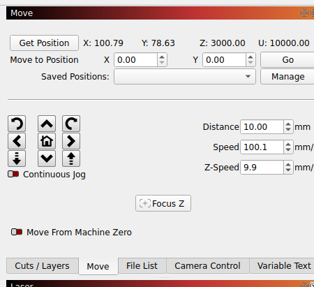
In the Cut/settings window is the move tab that has a get position button. This should populate the position data, mine does this automatically.
You can also enter where you want it to go, along with a save position for frequently used moves.
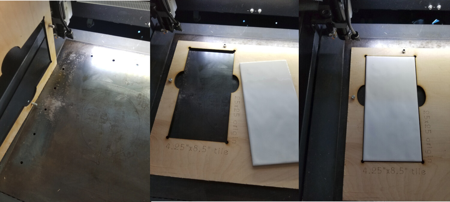
I have jigs for my machine. As you can see the top left corner of where the material will be is labeled as the origin. In the move window, I enter 25 and 25 for the X and Y axes and click go. I then push origin on the machines console. Don’t forget this… I know it’s easy to skip. This sets the user origin and I set start from to user origin.
I engrave the origin into the jig so I don’t have to remember the values … it’s on the right bottom of the cutout.
If you use current position and move the head at all, you’ve lost the position… with user origin it’s not a worry. This is maintained through a power shut down or a reset operation.
I also set the job origin to a top left selection.
You can also use the move laser icon You click on it, then click anywhere on your workspace it should move the head there…
You can’t zero these - user origin handles all of this fine. You just have to remember to push the origin button on the Ruida console.
The laser tools → materials test that @cggorman mentioned is probably more effective and doesn’t have the human error potential hand coding does. It is also probably much more versatile than you think… You can also save data in the process that you can call up and run with any material.