I’m cutting balsa wood and lite ply for rc airplane parts. I bring in a dxf from AutoCAD to cut my parts. I calibrated the controller using $100 and $101 to get a 1" square cut out. It cuts out at 1"x1" +/- .001. Then I import a 1"x2" part and cut it. Measuring the 1"x2", it comes out at .969"x1.951". Started having this problem just before my Eleksmaker board stopped working. So I assumed it could have been the board causing the problem. I replaced it with another 2 Axis Generic board with GRBL 1.1f and I still have the same problem. Open to suggestions.
I’d suggest you do your calibration on a larger square than 1x1. Any scaling issues will be reduced if you use a larger sample of your machine’s motion.
1 Like
Did you take the kerf into consideration?
It’s better to burn a thin line on the material so you can measure it accurately from center to center, without having to fiddle with the kerf.
I used a good-quality metal scale to avoid measurement offsets:
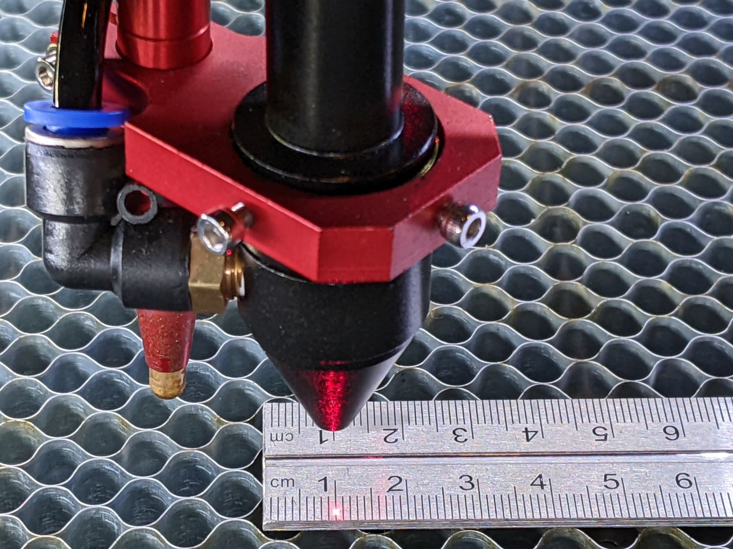
Once you get that set, then you can calibrate the kerf and get accurate cuts at any size.
1 Like
I tried the 2x2, when it is accurate the the 1x1 is oversize by about .020.
I agree with Ed here - the laser’s beam has a width that you need to account for in your scaling. If you’re measuring a cut item, you will need to add the width of the laser beam.
I have never used the kerf setting before and never had a problem with the size not matching the template on the screen. What is happening is, the more distance the laser travels, the bigger the discrepancy between the cut and the template. I don’t think the kerf size would increase or decrease for different size parts.
The kerf isn’t the setting. The kerf is the slot cut by the laser. The setting is intended to cut on the outside of the line so the finished shape is on size instead of down the middle of the line. At the same speed, kerf should be consistent and shouldn’t change width very much.
Your reasoning here is spot on.
If axis calibration was used to correct the size discrepancy caused by the kerf, the outcome would be close for objects that are roughly square or round. Axis calibration corrects distance errors proportionately; kerf doesn’t. This could be why the error would get bigger, while the kerf stays similar.
The way to reduce any error added to axis calibration by kerf is to engrave a large square with the lightest, thinnest line you can see with the Kerf offset shut off.
Then calibrate the axis based on that large square, because the proportional correction will be more accurate with a large square. When your square is perfect, measuring from the middle of the finely engraved lines, the axis calibration part is done. This takes kerf (and dot width) out of the equation altogether.
When you return to cutting, you’ll probably need to use the Kerf Offset setting. The setting tells LightBurn to cut outside the line by One-Half of the slot width. It’s the same as moving a jigsaw to cut outside the line (instead of on the line) by 1/2 of the width of the blade.
Now, here’s where things might get weird…
If the acceleration is set low, cutting a small square may not let the engraver reach its commanded engrave-speed when the engraver accelerates from a stop like a corner.
The GRBL controller will reduce power to compensate for the reduced speed (while accelerating and decelerating). Kerf can change in unexpected ways.
It may be worthwhile cutting concentric squares (smallest to largest) in 1/2" intervals up to 6 or 7 inches to show that the kerf doesn’t change much.
Kerf change will be seen on larger squares as a difference between length (or Width) measuring across the middle compared with measuring along the edge. It might be hard to see on a small square.
By cutting concentric squares, you can measure the inside edge of your cut and the outside edge of your cut and see how much can be attributed to kerf and how much may be calibration. With enough data, the effects of a rectangular shaped dot may be seen.
Two shapes wouldn’t be enough to fully prove what happened here, but you’ve absolutely demonstrated that something is not behaving proportionately.
You’re off to a great start.
1 Like
It will be a day or so before I can get to this, but I will let you know the results. Thanks for the info.
1 Like
So I created a 6x6 square and imported it. I adjusted the $100 and 101 until the engraved lines measured 6.0" in both directions. Then I did a 1" square and it measured 1.036 in the X and Y which is quite a bit of extra size for a 1" part. Just to see what happens, I adjusted the $100 and 101 to created an engraved 1" square. Then I engraved a 1x1, 1x2 and 1x3 on top of each other. Of course the 1" sides all measured 1" but the other lengths measured 1.000, 1.965 and 1.928. Not sure what I’m going to do with this information just yet. The discrepancy wouldn’t be to much of a problem If all my parts were around the same size, but I cut 1"x2" and up to 4"x32" and all in between. I don’ want to recalibrate every time I cut a different size part.
Changing your steps isn’t the way to solve this issue, I suggest you set them back to what they originally were and then use the kerf offset setting to accomodate for the discrepancy you’re seeing.
What’s happening is that a laser beam, though small, isn’t infinitely thin. When it burns through a material it removes some of it as it goes. The amount removed varies based on several factors such as the light source/wavelength, power, speed, material, and thickness.
If you’ve ever cut a piece before, you’ve probably noticed there’s some play if you put the piece back in the hole it came from. It wiggles to and fro a bit. This gap that is removed by the laser is called a ‘kerf’ - it’s the amount of material taken up by the tool. Think of cutting a piece of wood with a saw, you lose a bit of wood to the saw blade itself, so to counter that you were probably taught to start your cut on the outside of the line you need to cut to, not on the line.
When you run a job with no kerf offset, it’s like a saw blade cutting right on the line, the beam just traces along the centre of each line in your job, removing an equal amount either side.
When you use kerf offset you are telling the laser to run the beam outside the line you need to cut to, so that what you are left with is cut to your final specifications, similar to cutting with a saw the ‘right’ way.
When calibrating steps, pick the largest distances apart that are possible on your machine, and instead of burning all the way through, try just marking the material.
I loaded a trial version of Light Burn on another computer and calibrated to mark a 1" square on some plywood. I did a 1"x1" and a 1"x2", this time the 2" distance measured 2". Same process on the previous computer produced a 2" part that was .035 shorter (1.965).
Just for reference, I had cut out 21 parts for a project (these were all different shapes, not just rectangles) with a size range from 2"x2" to 4"x31" without calibrating anything and they all fit together perfectly. The 31" long part was only off by .032. A week later I cut out a couple of 1"x12" parts I had forgot and those parts were an 1/8" longer than they should have been and did not fit. Something changed, because I never had that problem before.
When you say that it measures 1.965", what measuring device are you using?
A dial caliper.
1 Like
This is exactly correct IMO.
Calibration is for positioning/moving the machine’s tool carriage an exact amount when commanded. Once the steps/mm settings are determined to move each axis an exact amount when commanded, it should never be changed… i.e. it is a function of the machine’s positioning mechanics.
Kerf compensation is not a part of the calibration process… it changes with each tool change. Kerf compensation is a function of the tool (even if it is a laser, it has kerf) attached to the carriage… and is specified during CAM operations for a given job.
Calibrate the machine’s positioning mechanics once and leave it alone… compensate for tool kerf during CAM on a job-by-job basis.
2 Likes
This problem seemed to start randomly. I still don’t why all the previous parts I cut were correct and all of the sudden parts were coming out to long. A 12.625 part was now 12.75 long.
I ended up reloading the previous version of software to see if that made any difference. I also engraved a set of tick marks every 1/2 inch for 12 inches and used that to set my steps until the distance was correct. Did the Y direction first and then the X direction. Now at 18" it’s only a 64th of an inch off, which is close enough for what I do. I also engraved the outline to the 12.625" long part and it came out correct.
At this point I going to say I’m back to where I was before the change in accuracy. So I’m good for now.
I’d like to thank everyone for their input on this, it was very helpful.
Thanks again
Tim