Camera Alignment Accuracy

How is your camera mounted? If the overlay is shifting there’s something going on. Typically this is from an unreliable ability to relocate camera to the same exact position and orientation, usually on lid mounted cameras.

The other major factor for fixed bed machines is parallax from different material heights.

Whats the code for flattening the fisheye lens out? Is it tied to bed size? It had to be. Will messing with the work area cause the math to flatten the fisheye differently? In the test photo the top left (origin) is perfect, and it slowly gets worse the further away from that point. This reads like an issue with the math for interpreting the fisheye curvature and getting it to align with the workspace.

No. All distortion correction features, as far as I know, are handled during lens calibration. Although thinking about it now, it’s possible that perspective correction may be handled during camera alignment.

If this were fisheye distortion you’d expect not a linear distortion on X and Y but rather a spherical distortion the farther out from center.

This isn’t likely a basic match calculation issue more than it is an accumulation of errors from lens calibration all the way to camera alignment.

It’s rigidly fixed. Impossible keep every project at same height. Just don’t know if I should bother realigning each time. I guess it would be practical if you are running a series of the same thing in a row.

At that point I think I’d relegate it to more a rough placement tool and use other methods to get fine-grained placement accuracy.

Or invest in a way to have a movable bed that allows for fixed distance to camera.

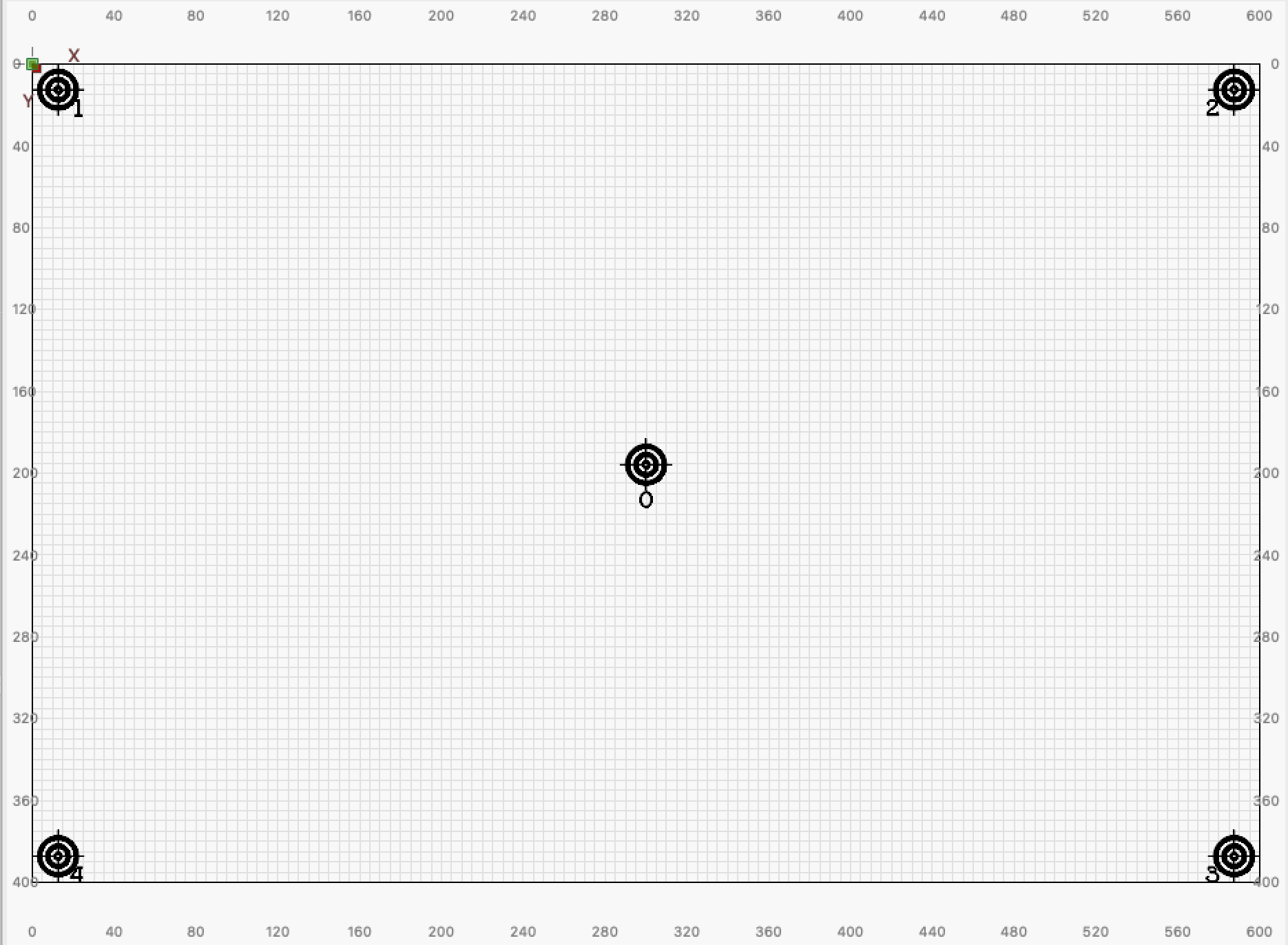
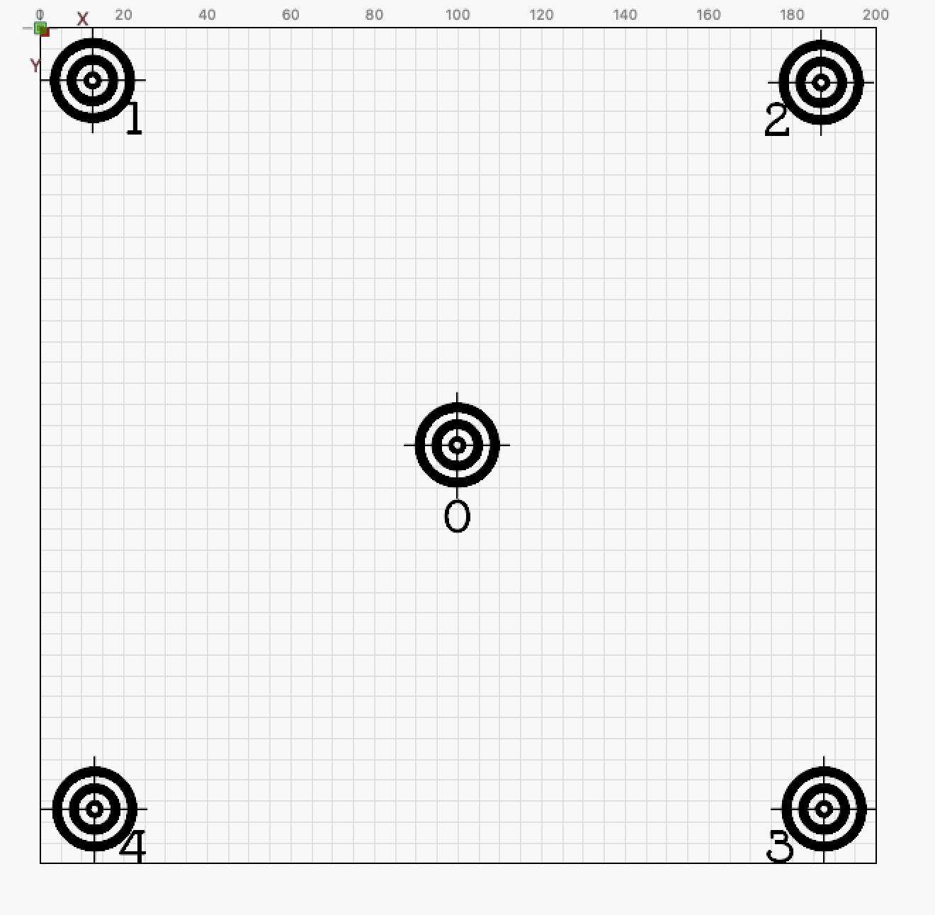
The reason for the “decrease” the area for e.g. 200x200mm is to keep correction smaller.
When I calibrate my camera to the entire work surface, which is my standard situation, I have to compromise in relation to error correction of the relatively large area. I start with T0 and hope it does not have a deviation or at least one very small, (+/- Few Tenth of a Millimeter). Then I measure in record 1 to 4. The average value I use for correction. (It requires Camera Alignment and Lense Calibration are in the best possible way before the fine tuning starts.)
When I want extreme account for certain tasks, I only check and adjust the “small” area I want to use, the variation is more manageable and faster compensated.
I have no idea if that’s the right way to do, but it works very well for me, with tolerances down to almost nothing.

Unfortunately not on Mac OS or Linux Ubuntu, here with me.

Yes. I was addressing the user’s specific OS.

First of all, Thank You for the link.

Regarding your approach, it makes sense and I did proceed with a similar approach; however, after few days of experimentation, I came to the conclusion that I may have to revisit the Alignment Process, and, consequently, decided to step back and revisit the basics:

  • If steps in the Alignment Process are not tight/controlled enough, then the process may not be predictable(Actually, I find that the Alignment Process is not tight/controlled enough, and the multiple approximate, manual steps, are error prone)
  • I’d rather consider ways to improve the (alignment) process than to check/test the accuracy, once the alignment is done

I will share my findings in subsequent posts

I would sincerely appreciate if the Lightburn Team can/would suggest solutions/workarounds to the below issue that is, most likely, negatively impacting all camera users.

The below photo illustrates how a 20mmx20mm square (in the Work Area, dotted green) maps to it’s etched image (Overlay); as of the Overlay, the bottom side of the etched image is linearly diverging
(Almost 0.5mm for 20mm; though some may argue that the error is below 3%, but it remains visible)
Single Square

In reality, as shown below, the actual etched image looks square
Firefox Square2

There seems to be a perspective in the Overlay???

1. I asked myself: Is the camera properly positioned so the camera capture is parallel?
After few minutes of trying to adjust the position of the camera, I realized that: What I see in the Camera Control window is always skewed, no matter how I adjust.
I took a Screenshot of what the Camera Control shows

2. I asked myself: Is the camera “distorting” the image?
I connected the camera to a Linux laptop [the camera is tightly fixed to the engraver and the camera/engraver/material did not move, I have simply unplugged the USB and re-plugged]
I took the below Screenshot; few differences

  • No skew
  • Brighter image
  • Sharper image (to some degree, it may be caused by the brightness; personally, I see some blur and/or loss of resolution)

3. I asked myself: Is is caused by the OS?
I added a Webcam Add-on to Firefox (that may or may not be the best one); the below Screenshot suggests that it is not caused by the OS. (Not as clean as the Linux one, but of higher quality than what is shown in the Camera Control window)

(Later, I have noticed a similar perspective in other photos shared on the forum and Lightburn official documentation)

  1. I tried to improve the quality of the capture in the Camera Control window, it turned Off “Auto Brightness” and Lightburn crashed, as shown below

To me this doesn’t look linear since the right side seems more distorted than the left.

I’d suggest rerunning lens calibration. If you haven’t already, adhere the calibration pattern to something rigid and known flat. Any wrinkles or distortion in the calibration pattern could lead to worse distortion correction values.

Then rerun camera alignment.

I’d suggest exporting your current camera settings in case things go south and you want to revert to the current settings.

The bottom line looks linear, you can check it with a ruler, but it does not matter.

You seem to have in mind the Overlay, that is impacted by the calibration/alignment process.

Let’s start with the basics: Can we have a clean capture in the Camera Control window before starting the calibration/alignment process.

I have provided enough evidence to show that the capture in the Camera Control window is of poor quality.

I appreciate your effort, but I was expecting more than a standard answer, that we all know.

Repeating the calibration/alignment process and hoping for the best, may not work if the camera capture is poor.

As it is, the camera calibration/alignment process is not tight/controlled/automated enough to guarantee predictable/repeatable/accurate alignment.

I didn’t address the Camera Control window because I’m not familiar with the full relationship with what is shown there vs what gets to the overlay. We know that the view in Camera Control window is not distortion corrected so is likely to have little processing applied to it. The image is certainly not being rotated slightly there. It’s possible that any differences between video views is due to the particular video mode being shown.

Additionally, there’s really little user control for what you see there so from a practical perspective it’s likely more expedient to focus on what can be controlled which is the quality of the captures during calibration, especially if you’re leaving things on the table today.

But you do you.

I am expecting a well defined practical solution, to a well documented/defined issue.

Nobody mentioned “distortion correction”, “rotation” (a skew is not a rotation). etc. etc.

The issues are obvious

  • Skew
  • Brightness
  • Loss of sharpness (Maybe some blur/reduced resolution???)

I think it does not make sense to dig much deeper into the matter right now because at LBX it was announced that the camera feature is greatly extended and completely reworked. So the current camera feature, and alignment procedures etc. will be obsolete soon. There will be features like continuous alignment and calibration, marker tracking etc.

Thanks for the sharing the information. Is there a roadmap? ETA?
For me, this is a show-stopper.

I can’t say for sure but I don’t believe “soon” was ever specifically mentioned, only that it was actively being reworked. Keeping in mind that any new approach is likely to have its own quirks and issues to be worked out.

In connection with the periodic cleaning of the machine and inspection of focus and camera adjustment, which was today, I did a complete new camera calibration/setup. It was not strictly necessary, but with all the discussion about camera function and lack of precision, I will test my system with a freshly adjusted/calibrated camera and also test my beam alignment, which also got an overhaul today.
After LightBurn’s standard camera setup, which took me approx. half an hour, I engraved some scraps of 3mm plywood with simple crosses. It was not intended that the crosses should be perfectly in the center of the discs, but only to form a better visibility for the test itself. The whole test is done only with the “camera system”.

I randomly threw the discs with the crosses on my machine bed, turned off the light in my workshop and tried to hit the crosses with new crosses as best as possible. Then I measured the deviation with a caliper. The worst deviation was 0.65 mm, otherwise I hit the spot fairly well.

I am confident that if my camera light calibration problem is solved once with the new version of the camera tool (hopefully) then an even better result is possible. Bottom line, a deviation of 0.65mm without me having fine-tuned the system is very satisfactory and absolutely useful for my work.

It is not intended as a discussion contribution, but more as my documentation of my experiences on the theme.

1 Like

Again, Thank You for sharing your findings.

As I see it, your posts are valuable/genuine contribution, they are based on real/focused/well defined work/experimentation, as opposed to vanilla/boilerplate/vague suggestions that can be easily found using search/google.

As an engineer, I appreciate the way you proceed and sincerely appreciate your contribution.

I hope that it will be the case, and Lightburn will address the shortcomings of the current implementation.

My Use Case is simpler than the (more generic) problem that you are addressing; however, unfortunately, my Use Case does not tolerate a 0.65mm error, I can’t afford taking the chance of ruining a $15K granite stone. A gap 0f 0.2mm will/may be visible as a black line.
(To remind, my goal is to align a slice of photo with a previously etched slice of a large photo, about 72x36 inches)

In some cases, in my test trials, I was able to achieve below 0.2mm accuracy, but it’s not repeatable; the current implementation is not repeatable/tight to guarantee reliable/predictable results. I need a repeatable/reliable process with a well known, predictable margin of error.

I haven’t given up, but I’m coming to the conclusion that, as of the current implementation, the camera feature of Lightburn may not be good enough for my Use Case???

It is over the entire machine bed, 600x400 mm, without compensation(!)

Although I am very happy with LightBurn’s camera solution, I would not use it for the projects you have going on. It is a big difference to engrave 100 pencils or the expensive material you have on hand