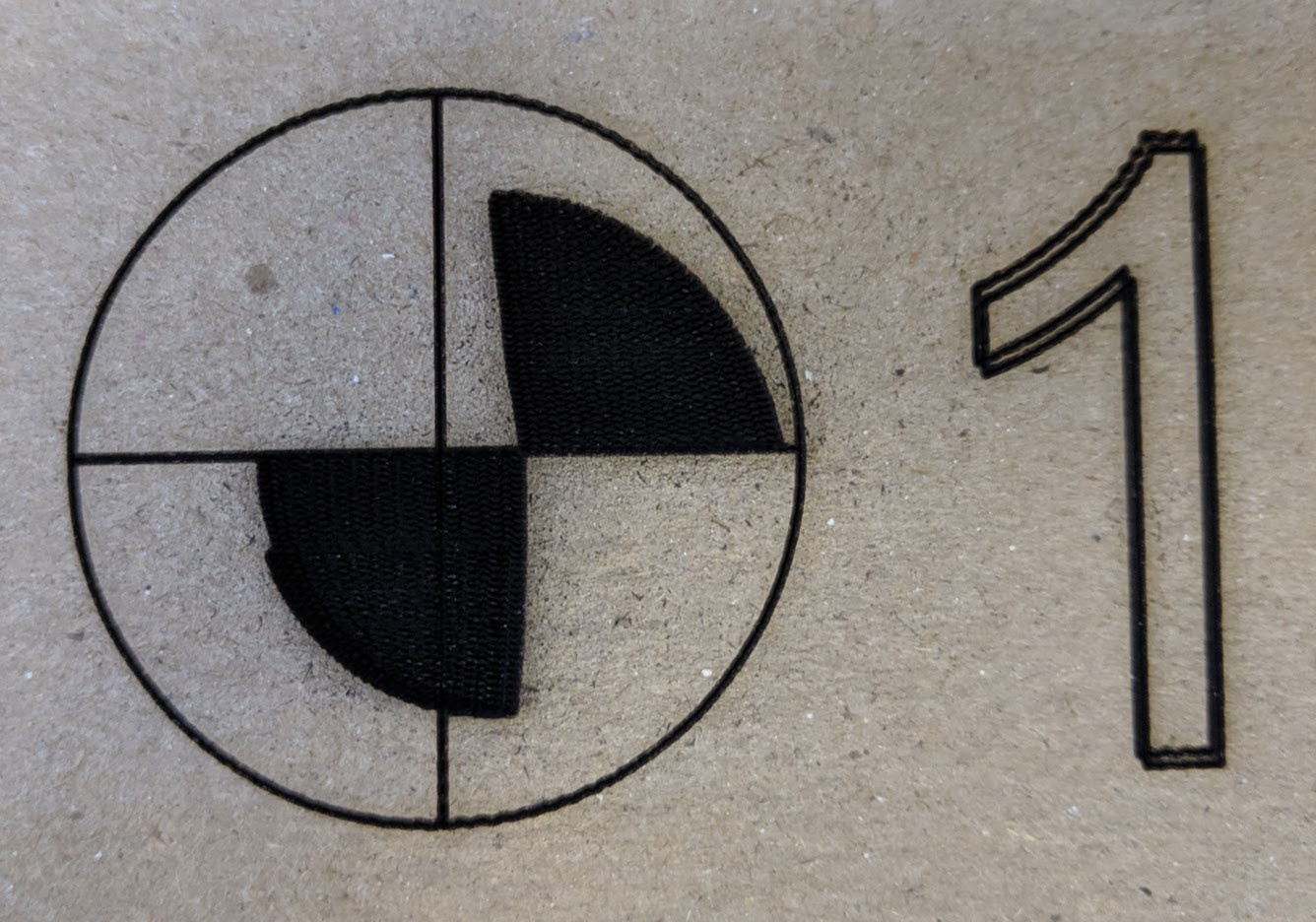
Now the fill pattern I think I saw a setting about adjusting for the raster scanning being ahead or behind of where the laser fires… though as you can see they are not consistent.
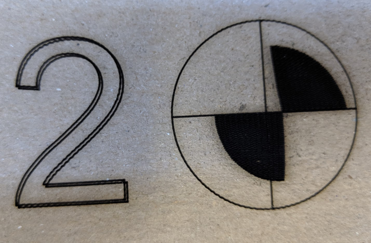
But then the second thing is that you can see the 2 outlines of the numbers are slightly off.
Could this just be slop in my system?
The weird thing is I just finished the alignment wizard but using the lines in the circles, not the fill portion and it seems to be spot on.
I might suggest removing the filled portions from the test pattern as they don’t seem to be required and they take up time.
I stand corrected, the alignment is spot on in the center of the cutting bed. But off by up to a couple millimeters in the corners. Which honestly, may be because my cut area is 1200x600mm
If I have to use the center area for camera aligned stuff, it’s not the end of the world.
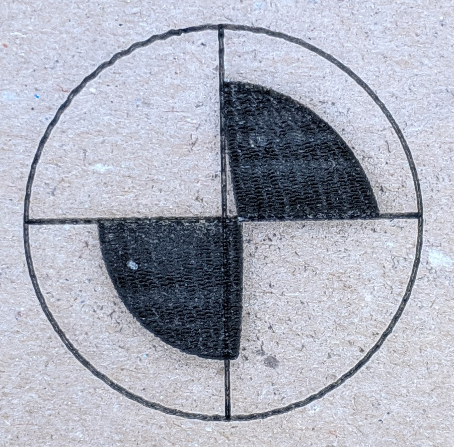
Did you notice how much wobble you have with the outer circle target at 5 to 7 o’clock and also at 11:30 to 2? I see it in portions of both the printed numbers, too.
The shape of the quarter section shaded areas is also totally distorted.
Yeah, I’m aware. My laser has a pretty pitiful motion system that can’t really go much above 15mm/s and I was doing this at 30mm/s. I knew there would be some wobble. But I’ve never seen it get that distorted.
The numbers are two overlaid paths, with one shifted down and left slightly to make them darker, so that offset is expected.
That slant in the scans is really weird though. Is it possible you have motor drivers that need “rising edge” for steps, and you’re sending “falling edge”?
Uhhhhhh… had no idea that was even a consideration.
I’m using the Cohesion3D LaserBoard and DM542 drivers (as recommended by Ray).
I do not see anything in the Smoothieware config to specify rising vs falling.
However, I do see that the datasheet shows a common anode vs common cathode wiring setup… I followed the C3D instructions for external steppers but it’s entirely possible that the +/- inputs needed to be swapped on the DM542 compared to what was documented for the one’s C3D sells. I’ll pop my machine open tonight and see what I can figure out.
C3D LaserBoard uses hardware open drain inverters to create a common anode setup on the drivers.
When you are checking, also check if any of your step pins in the config file have a ! after the pin assignment. Can you tell each axis to jog a distance and measure that the distance is indeed correct?
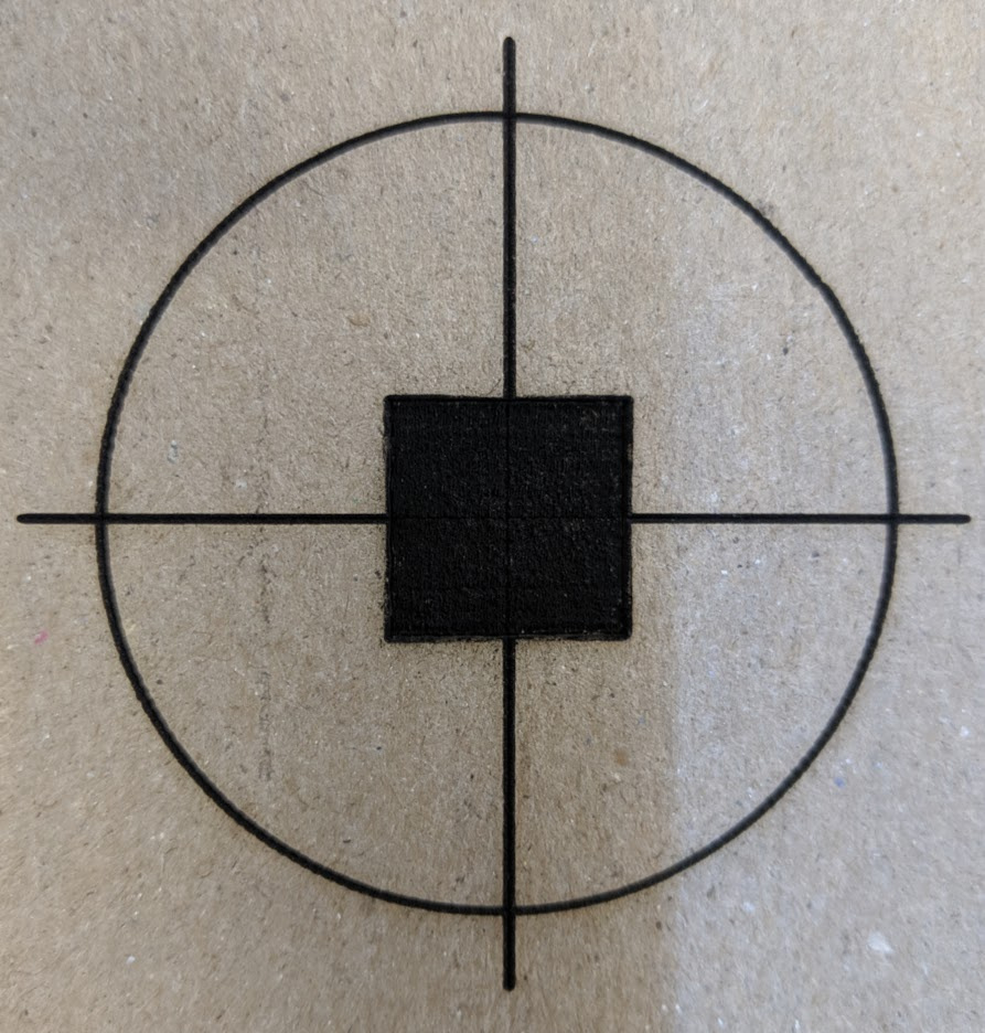
@LightBurn - Do you have the camera alignment file separately and could send it to me? I’m trying to reproduce the issue without going through the alignment wizard again but it works fine every time. For example, this was done at 120mm/s which is much higher than I ever used to run this machine with the old controller and software:
Perfect. There’s no artifacting on the square at all. I also tried with a filled circle in the middle, same thing. Looks perfect.
And I’ve even tried cranking the speed WAY up, thinking that the alignment wizard was maybe ignoring my speed… but I have the acceleration in my config set to 500mm/s/s (as opposed to the LaserBoard default 2500mm/s/s as it was in my old controller’s firmware, that it’s never actually reaching those higher speeds. I’d say it’s maxing out at 100mm/s on a 50mm square object.
So this leads me to believe that it’s either something with the vector file used in the wizard (and something weird with my machine that only shows up with that file). Or the wizard is doing something weird on the gcode output… having the vector file used would at least help me confirm it is or isn’t that specific design.
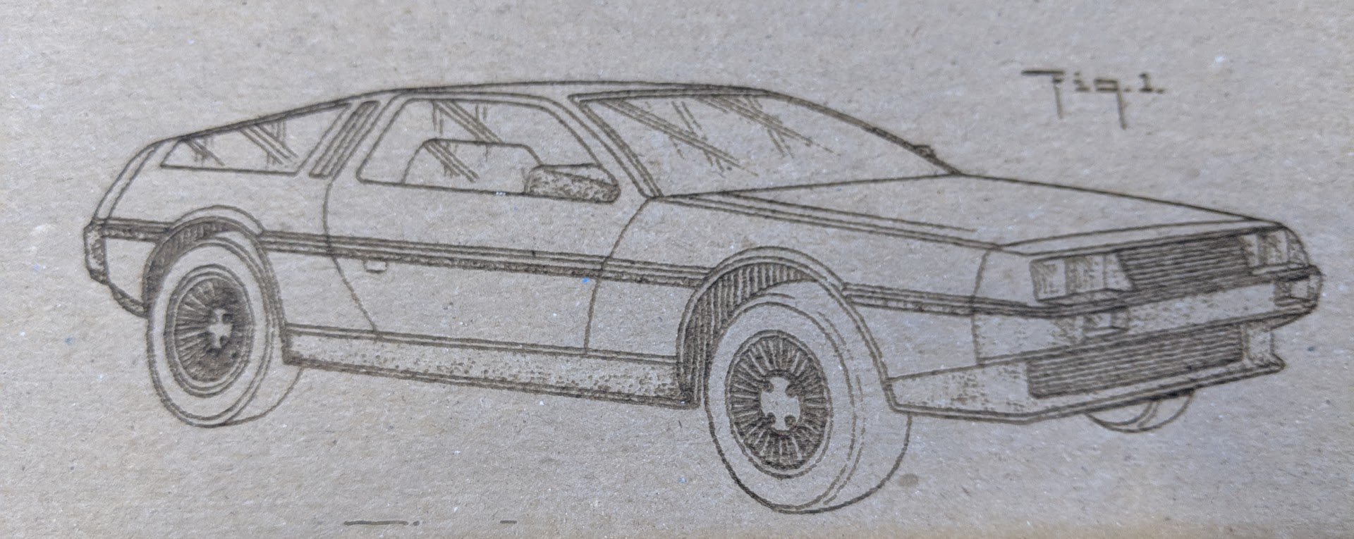
I even ran this raster engrave and it’s absolutely perfect. Zero evidence of any slop in the system or the laser firing at the wrong time.
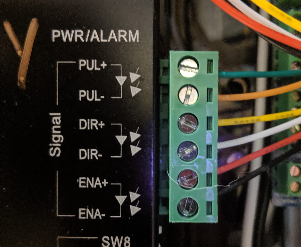
And @raykholo - I’ve double checked my external driver wiring, and it matches (at least per the labels on the DM542) exactly the wiring you have shown in your docs:
It’s flipped upside-down, but same order. Same colors to same labels.
So @LightBurn this is why I wonder if it’s something specific to the alignment wizard.
If you guys have any specific ideas, great. If not, it seems to be working otherwise and maybe I can pick this up in the future and debug in detail for you.
@LightBurn - What’s the max size laser cutter you’ve seen used with the camera? Maybe it’s just a matter of where I’ve mounted it but I cannot figure out why it only works in the middle half. Basically a ~400x600mm area out of the 600x1200mm full area. Tried recalibrating a couple of times to no avail… still off by an increasing amount up to ~3mm at the edges.
@LightBurn & @raykholo
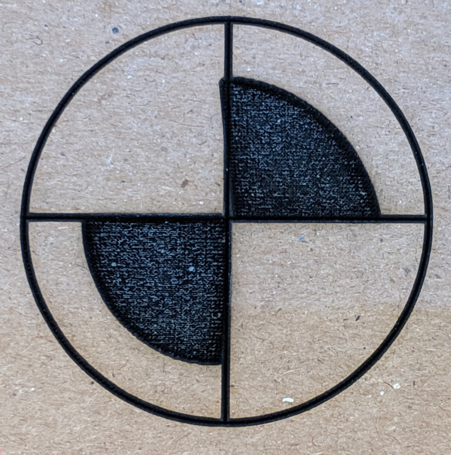
Ok, so I’ve tried the supplied camera alignment file and I can confirm it’s not related to the file or any specific settings. After I knew I could reproduce it with the full file I trimmed it down to just one of the targets and started testing. A wide variety of cut settings gave roughly the same results with that weird slant.
Next I thought I’d try with the settings from the provided alignment file but with something else. First I tried a simple circle and that turned out fine. Even with the outline traced afterwards, it lined up perfectly. A square worked fine as well. Even a basic triangle was fine.
So then I thought I would rule out that it’s the file given (don’t worry, I trust you @LightBurn, just gotta due my due diligence) so I redrew the target shape in InkScape and ran that… sure enough, it also has the same issue.
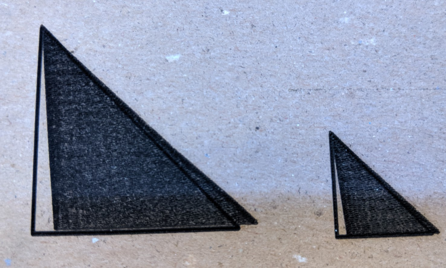
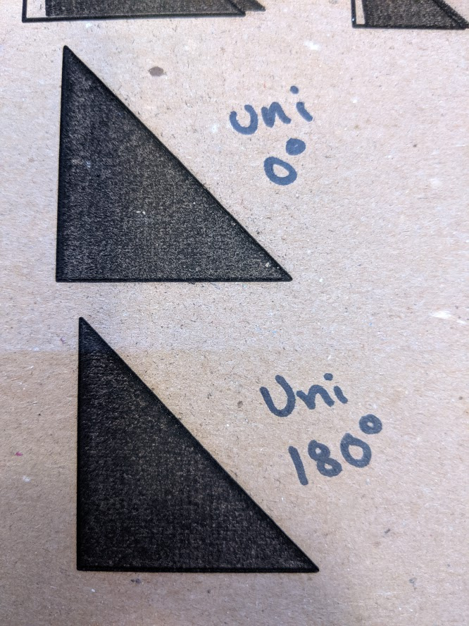
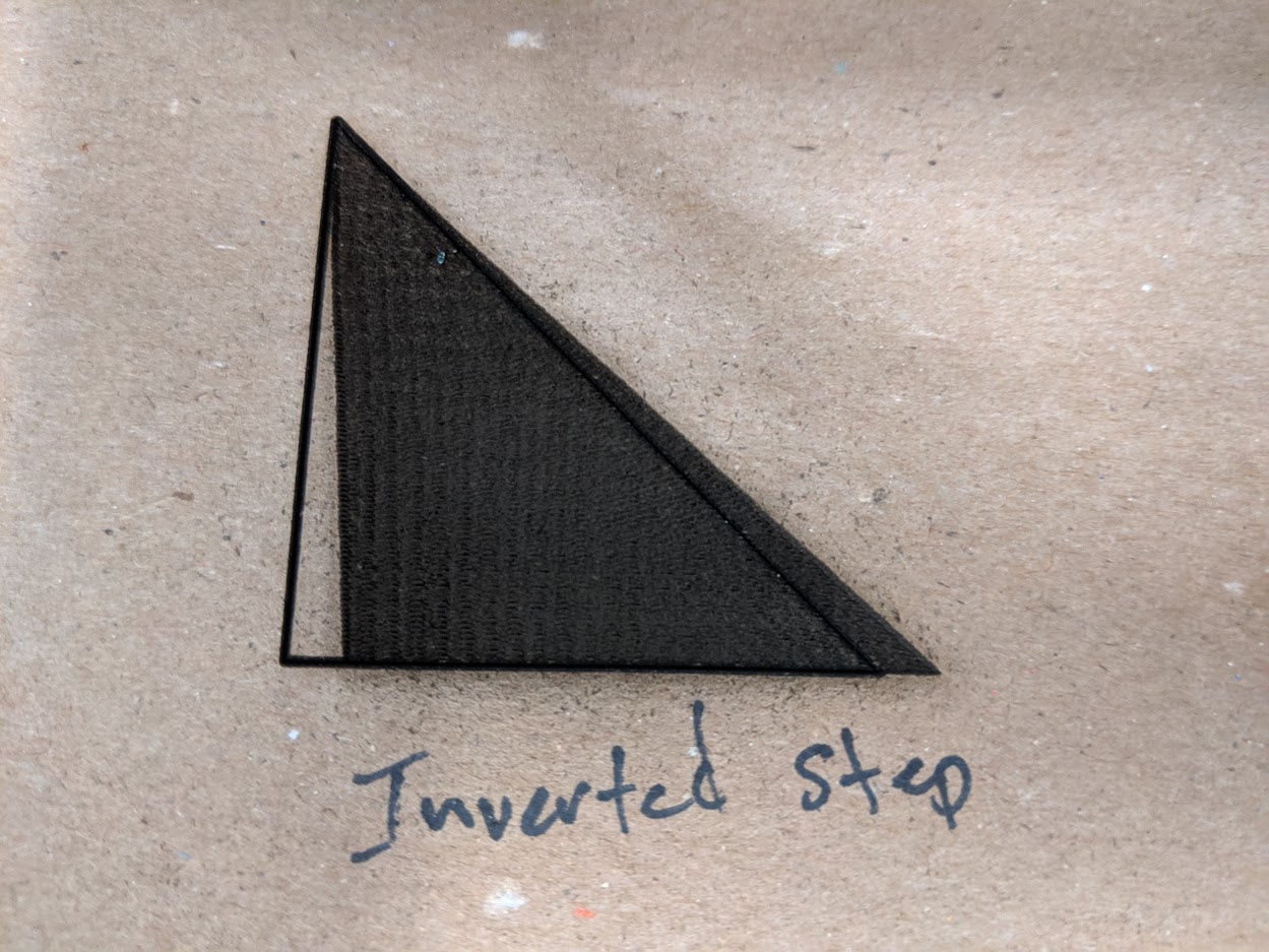
Given that it’s speed related I wonder if it’s semi related to the scan offset option that’s available in device settings. It does seem like the laser is lagging ahead or behind. But it’s weird that it’s specifically with pie shape. On another whim I wondered if it required having the radius on the long side, so I tried it again with a right triangle this time (last triangle was equilateral). And sure enough:
And the problem even scales with size. What’s weird is that the laser was firing in both directions so I’m not really sure how to tell if it’s firing ahead or behind where it should. And more… WHY only with this type of shape.
Any thoughts?
At least basic cutting and anything that’s not this specific shape seems to work without issue
Ok, that is bizarre. The slant I’ve seen before, when the step signal and motor driver don’t agree on whether it’s the rising or falling edge that signals the step. BiDir turned off means you get a sawtooth traversal instead of a square wave traversal, so that might still be the cause. See if there’s a way to invert the step pin output (which controller / firmware are you, Smoo? If so, I think it’s just ! after the pin).
Yep… I’m using the Cohesion3D board with SmoothieWare. Out of town for a few days but I will try inverting it when I get back. At least I have a specific way to reproduce it now.
Updated config looks like this (just adding the ! as discussed on the step_pin)
alpha_step_pin                               2.0!              # Pin for alpha stepper step signal
alpha_dir_pin                                0.5              # Pin for alpha stepper direction
alpha_en_pin                                 0.4              # Pin for alpha enable pin
alpha_current                                0.4              # X stepper motor current
alpha_max_rate                               24000.0          # mm/min
alpha_acceleration                           2500             # mm/sec²

beta_step_pin                                2.1!              # Pin for beta stepper step signal
beta_dir_pin                                 0.11            # Pin for beta stepper direction
beta_en_pin                                  0.10             # Pin for beta enable
beta_current                                 0.6                # Y stepper motor current
beta_max_rate                                24000.0          # mm/min
beta_acceleration                            2500             # mm/sec²
`

This makes me wonder if it's just something weird with my machine... slop in the motion system or something? Sadly I can't really try it with the old control hardware without completely undoing all the work with the C3D board.
Double check that I got that invert right - it should change the output, and doesn’t appear that it has. It’s not slop - it wouldn’t be that perfect, and wouldn’t be cumulative.
It might need to precede the pin number, not follow it - worth checking. As I said, I’d expect that change to alter the output, but it doesn’t look like it did.