Camera alignment fails after pressing "update overlay" button for 1st time

Hi Mikey

Not at all - I am grateful that you took interest and got involved. The more different perspectives on an issue the better. You never know when you might be missing something which seems trivial but could be the answer you are looking for

thanks

Hi

I already checked (and played around with these) they were mentioned earlier in the thread.

After alignment and the problem was present they were all set to zero. I tried adjusting them but did not resolve the issue so I reset them to zero again

sorry ill rephase that check you bed size in advance settings for both x and y

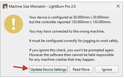
LightBurn doesn’t change firmware settings on its own, but > 2.0 will warn you if the firmware settings and Device Settings don’t match. See here
Clicking “Update Device Settings” will update the Device Settings in LightBurn, never the firmware settings on the controller.

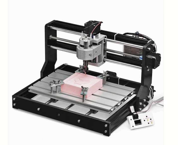
@traynor.dg Are you using this Sainsmart 3018 Pro?

The Bed-Slinger action of the Y axis is likely causing the shift of camera Overlay!
You’ll need to jog the Y axis to zero before capturing the overlay.

Can you show us the camera’s unprocessed view when the machine is at 0, 0?
It should cover the entire workarea and some extra on the sides.

Seeing that you had a mirrored output at first, you probably found this troubleshooting docs page:

Does the machine jog in the correct directions now?

That’s perfect. It’s recommended to engrave the targets covering the larger part of the workarea.

Hi Terry

yeah I have checked the bed sizes

Physical bed size is 290mm wide and 170mm front to back

when doing the alignment I used 20mm for feature size and entered 290 and 170 as the pattern sizes.

The pattern printed on the target sheet (2mm thick MDF sheet) without error and within the bounds of the bed.

The alignment pattern was fully visible and I could click on each of the crosshairs (1 to 4 in order) without having to make any physical movements to the bed or the laser module.

the alignment process when it finishes leaves the last camera view (ie the alignment view) in the main Lightburn window.

if I do not press the “update background” button I can draw shapes in the workspace (eg a square) and if I then go to the laser control tab and press “frame” it frames the target perfectly.

The only conclusion I can come to at this point is that the alignment is correct. For example i can move the square shape that I drew to another position in the workspace and it will again frame correctly. In fact i used the patterns created in the alignment process as targets for the framing so that i could visually confirm the accuracy.

The problem only presents itself after pressing the update button.

I will add the camera again a little later and copy in some more pictures to try to demonstrate the issue further,

@traynor.dg
I’m just seeing that you are using a Head-Mounted camera:

We’ll need to see how and where you mounted the camera! Please send us a picture.

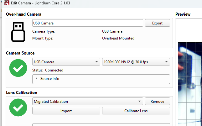
Can you send a screenshot of the Edit Camera dialog?

HI Aaron

thanks for coming back to me

Not sure its that brand but its definitely a 3018 pro

Before adding the camera I run a home ($H) command so that the device knows exactly where it is - I have zero position switches on x,y and z axes

I will take some more pics when i run through the “add camera” again a little later. I think I provided the view you talk about in the earlier posts (maybe the original one) - but I cannot review the earlier posts whilst typing this reply.

I hadn’t seen that guide before - so thanks for directing me to it. I will take a look after posting this

quick question regarding orientation should the front of the device (ie the home position of the laser be viewed in front left of the camera image - don’t waste time answering this if the info is already in the guide :slight_smile:

You guys have been so kind trying to help me resolve this hopefully I cant get this over the line. I might go “radio silent” for about a week after today as I will be on holiday and probably wont have access to the forum

hi Aaron

will do - might be a slight delay getting the screen shot info back to you, i will re-add the camera in a while

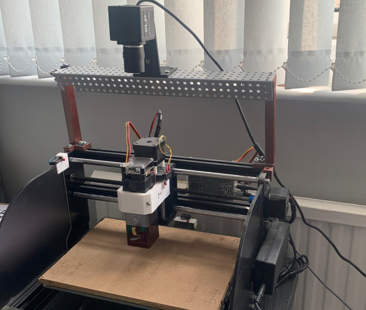
in the meantime this is my camera mount

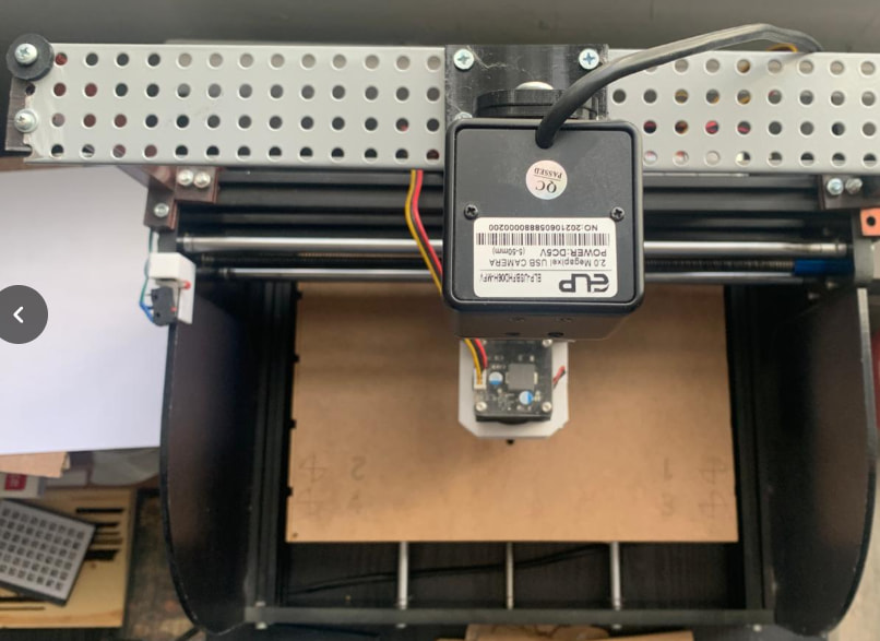
and from above

Thanks for the pictures. That mount looks sweet.

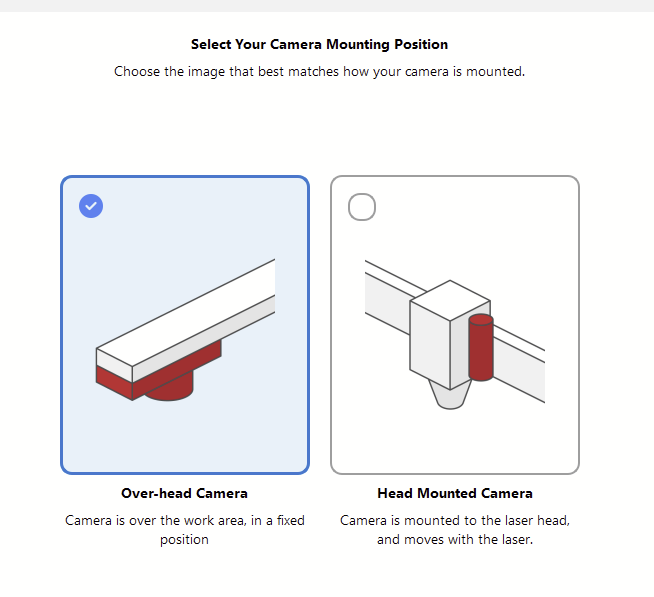
You’ll need to remove the camera and add it again, choosing “Overhead Camera” in the third step here:

Hi Aaron
I have always selected overhead camera - does it show something different in the screens ? Let me know if I am missing something

I have gone through the process again and tried to capture as much as possible - looked very promising but ended with failure. I have created a PDF document which I will try to upload. If I can’t then ill add them manually as a post

looks like PDFs are not allowed :slight_smile:

Your previous screenshot tells otherwise.
If Overhead was selected, the default camera name should be “Overhead - USB Camera”

I’d love to see that to investigate what might have gone wrong.
Can you paste the contents of the PDF here?
You can probably upload it, if you change the file ending to .txt

The camera’s orientation in regards to font and back doesn’t matter. This will get corrected after selecting the targets in the correct order. But the targets (numbers) can’t be mirrored.

Hi Aaron

Lightburn Camera Alignment

To try to be as comprehensive as possible I created 35 images as i progressed through the process - unfortunately after adding them all to this post and pressing submit the forum portal said I could only upload 4 - so have placed figure numbers where the images should be and I will email you the PDF. Not sure if you also want that info available to other members too to aid cklarity

to recap
I am running windows 11 and Lightburn (v2.1.03) and cannot thus far correctly align the camera

Also of note, there are 2 USB cameras on my PC -which is relevant further down when camera selection is reached - unfortunately windows has labelled them both “USB camera”

  1. A webcam used for video calls above my display
  2. The USB camera mounted above my device

Remove existing camera from lightburn

Close lightburn software and restart it

On restart this window popped up – have restarted lightburn previously and have never seen this message before

Figure 1

Device seems to be “Homed” by lightburn at startup – there is no camera added at this stage. Workspace dimensions show correctly as 290x170

Figure 2

Device Settings
Figure 3

Figure 4

Figure 5

Figure 6

Machine Settings

Figure 7

Now adding the camera

Laser Tools > Manage Cameras

Even though I had previously removed the camera the USB camera was in the list – so I removed it again

Select the USB Camera and press “Remove”

Figure 8

Now the list is blank but the camera control window is still streaming live

Figure 9

I pressed “Add New”

Figure 10

I pressed “Select” for the USB Camera

Figure 11

Figure 12

The camera listed here is the webcam above my display screen – even though I removed the overhead camera from lightburn it was not listed here and yet the camera control screen is still showing a live feed from the overhead camera – something weird going on.

I closed the manage cameras dialogue window and pressed Manage Cameras again

Figure 13

The camera has appeared in the list again without me adding it - weird
This time I selected the camera and pressed edit and got this view

Figure 14

I repositioned the target piece of material so that it was aligned with the front edge of the bed
I then pressed “Align to Workspace” button

Figure 15

Figure 16

Figure 17

Figure 18

On this screen I used machine control to adjust the height of the z-axis to be 5mm above the material surface and set power to be 45%

Figure 19

Once finished I clicked on Next and got this view – no camera image at all!!

Figure 20

I tried to click back then Next again – still no image
So I kept clicking back until I came back to this screen again

Figure 21

Then I clicked the following (ive not included screenshots since its a repeat of those steps above just without the burning of the pattern this time)

“Align to Workspace”

“Next” on the welcome screen

“Next” on the select alignment screen (manual chosen)

“Next” on the Manual Alignment Wizard screen

“Next” on the Alignment Pattern Setup screen (parameters were as before 20, 290, 170)

“Next” on the Burn Alignment pattern screen (without burning this time – the material was in exactly the same position)

Now I get this screen with the camera image – note that the laser module is back in its home position

Figure 22

I used the machine controls to get this view

Figure 23

Note that the number 4 in image top right corner is physically in front right corner (ie home position)
Then I clicked each number in turn and then “Next”

Figure 24

Figure 25

I must admit that I do not know what is meant by “Verify that the alignment is correct in the warped preview”. I mean it looks OK – it doesn’t fill the complete workspace but now the number 4 is in bottom left which I presume is the home corner and corresponds to the physical front left bed.
I am open to having misunderstood the meaning though

I clicked next

I have just noticed that on all previous alignments after clicking on the 4 points the alignment process asked me to draw a rectangle covering the useable area – it did not ask for that this time

Figure 26

Then click finish and then finish again to exit the “Edit Camera” Dialogue

Figure 27

Then “OK” to exit the “Device Cameras” Dialogue
This is the main window view with camera control tab open to right side

Figure 28

Since the main Lightburn window does not show the camera view of the bed I then pressed the “Update background from the Camera” button

Figure 29

And get this view – which actually looks promising since the main window and the camera control view are the same (feeling hopeful…)

Figure 30

So I drew a square around the arrow near bottom left corner

Figure 31

And in the laser tab I pressed frame to see if it positions the frame correctly on the bed

Success!! (feeling very hopeful..)

Not satisfied I moved the square to cover the 3 in front right

Success!! (now getting giddy with the success..)

I will close Lightburn and re-open without changing anything or moving the material

On opening Lightburn it homes the laser module

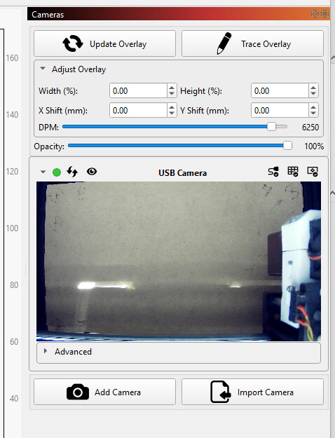
This is the view with camera control tab open

Figure 32

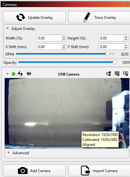
Then I pressed the “update background” button and its looking good (now holding my breath..)

Figure 33

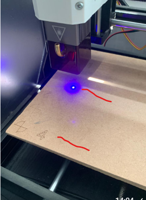
I drew a square around the “4” and pressed frame

Figure 34

The “Frame” is approx. 80mm “above” the target (ie Y axis) marked by the red lines. The x-axis looks about right. I didn’t want to disturb the material by measuring more accurately.


Figure 35

Must admit to feelings of deflation and somewhat turning the air blue - but no-one else heard so that’s ok :slight_smile:

any suggestions for next moves - or if I’ve have missed anything interpreting the instructions
regards
dave
hi
i could upload the PDF nor create a post with more than 4 images - unfortunately only discovered that when I pressed the submit button. PDF has been sent to the support email address

let me know if you need more info

Are there any logs that might help with this?

as you see from the POST it seems to work and then it suddenly doesn’t.

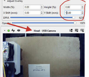
just in case anyone wonders about the “adjust overlay”, they are still set to zero

hi Aaron

Im convinced that every time I was asked that I chose overhead camera (although I would not rule out a bit of a brain fart one time - Ive added the camera so many times now)

At the moment it just says “USB Camera” in the Cameras tab

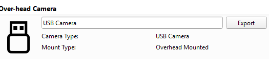
whereas if I go to the “Manage Cameras” option and choose edit - it shows “Over-head” Camera with Mount type “Overhead mounted”

i never got that pop up , but my firmware def changed to x 400 y 400 after the update , an i def didn’t change any thing. it was set at x 400 y 850 over 2 years when i put the extension kit on it

only reason i went looking in advanced was an update did the same to my piece of junk xtool i used to own ,with an extension when did Lb update it defaulted to standard size 400x400 didnt register it had extension

David,
Thank you for sending us the PDF with all the screenshots.
It’s an interesting case I haven’t thought about yet!
Since your “bed-slinger” type CNC moves the bed back and forth, the camera’s view effectively changes.
I believe, that was the reason why your overlay didn’t cover the entire area. In the first picture of this thread, we can see the head is in the top-left position in the workarea. (Bed moved towards you).
I would have expected the overlay to only display the top part here, but other things were wrong initially. (Using a head-mounted setup, and the G54 offsets weren’t factored in.)

So it’s important that the machine is always at the correct location when capturing the overlay.

One important thing:
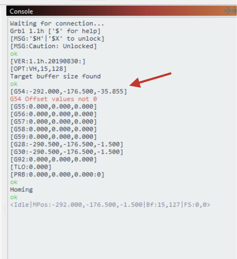
Your machine uses a G54 offset:

You’ll need to clear those offsets by entering this command in the console window:
$RST=#
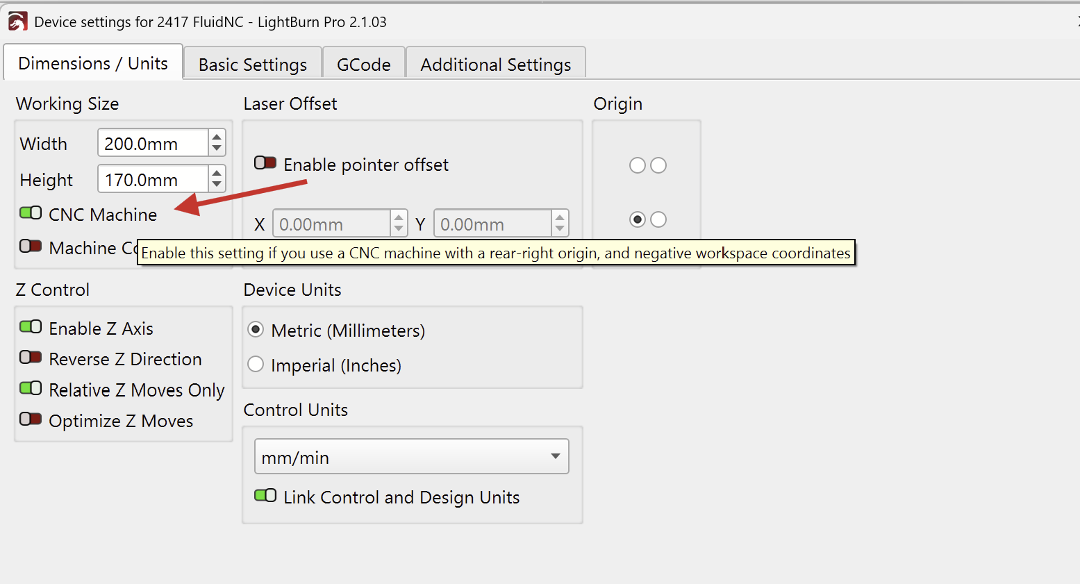
And enable “CNC Machine” in the Device Settings here:


From your description in the PDF, I wasn’t sure whether you engraved a new set of targets when you re did the Alignment.
You can use the old targets and place them roughly at the same spot for a quick test, but you’ll need to mount the board securely and engrave a fresh set of targets for an accurate alignment.

This docs page is important when using a CNC machine with a laser:

Mainly:

  • You’ll neeed to enable Laser Mode $32=1, as explained in the link above.
  • Does your machine have limit switches? The last section of the linked docs page is worth reading.

I have a small desktop CNC machine that I can dust off when I have a chance and mount a camera on.

Let us know how it goes! I’d be happy to help you find the right settings. It should be doable!