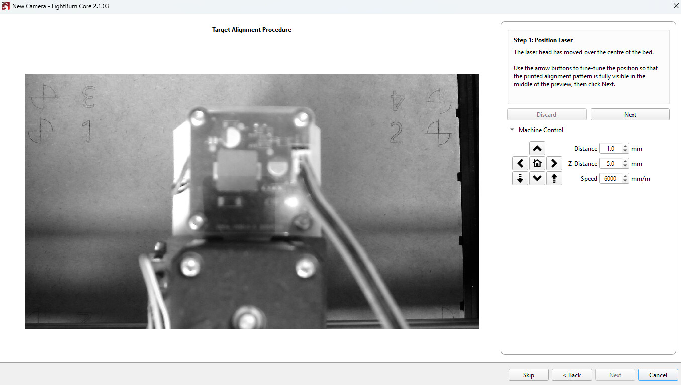
I just updated to version 2.1.03 and wanted to setup existing overhead camera again to ensure correct alignment. Running Lightburn on Win11.
I started by removing the camera and then re-added. I calibrated the lens and then ran the alignment (manual process).
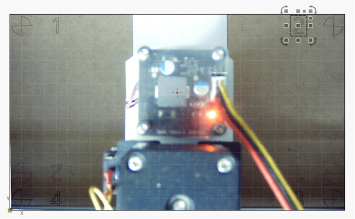
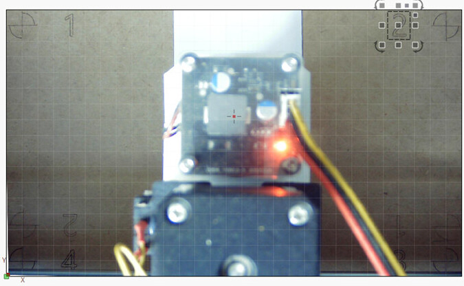
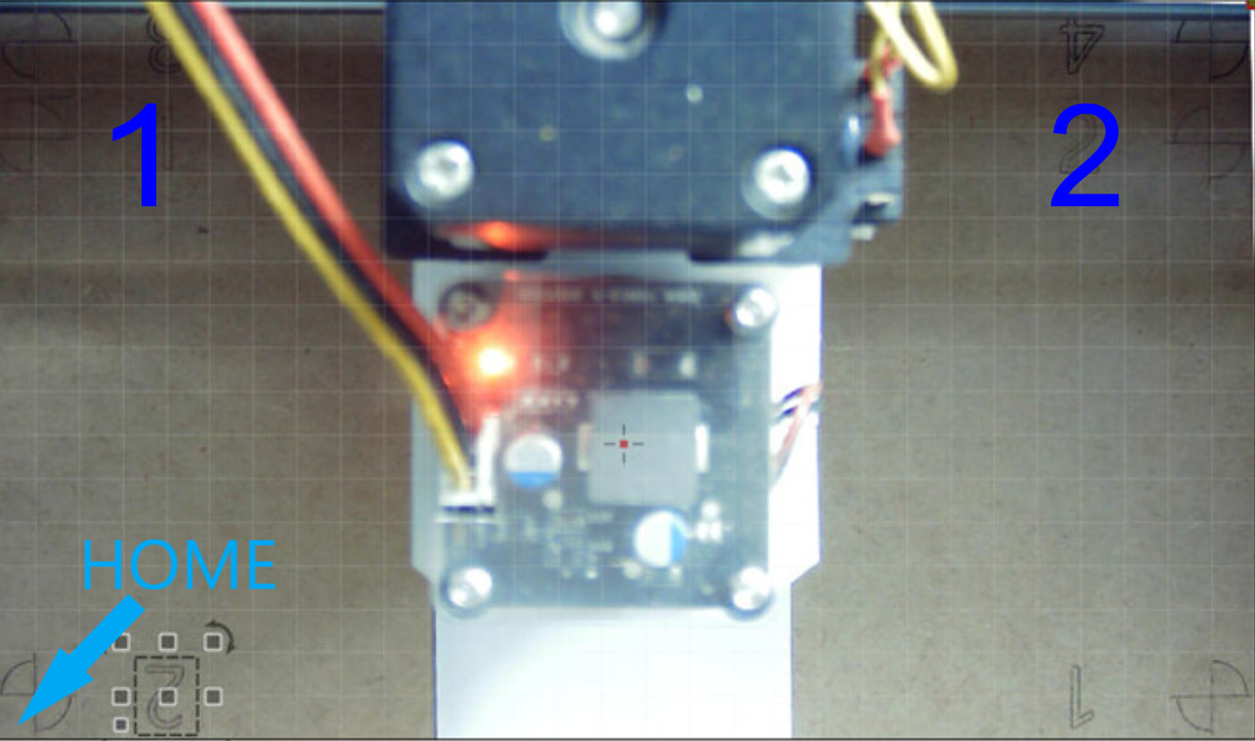
Immediately after completing the alignment process the background view in the main window still shows the full alignment pattern on the workspace - see image below
At this stage I can draw a rectangle and move it using the camera view to surround each of the 4 numbers (1-4) in turn. At each of the 4 points if I select “Frame” from the laser control tab the laser correctly frames the rectangle around the digit. Which I take to demonstrate that alignment is correct and working perfectly.
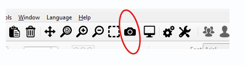
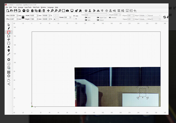
If I then press the “update the background from the camera (ALT-C)” icon on the tool bar - see next image for clarity
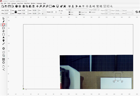
I get this view - see image below. The dotted rectangle is still in the same position where it surrounded the digit “3” and this is in agreement with the rectangle indicating the workspace (workspace size is 290x170).
The white square seen to the right hand side is a target to print.
if I try to position an image using this view and then press frame it no longer matches the partial camera view
My presumption is that since prior to pressing the camera overlay button the camera image is fully aligned to the workspace and i can target any position that the setup is correct and able to perform as expected.
The above steps are repeatable, ie if I remove the camera and repeat the process from the beginning i get the same results
This large spectrum you write about, I would not have expected.
But I still believe that a successful lens calibration and correct workplace alignment is not as far out of “normal” as we see here in this example. Up to a few mm I will understand, (but personally not accept), but -50 or 100mm …
What is the reason for this enormous deviation?, my fine adjustments have always been in the sub 1mm range.
Hi
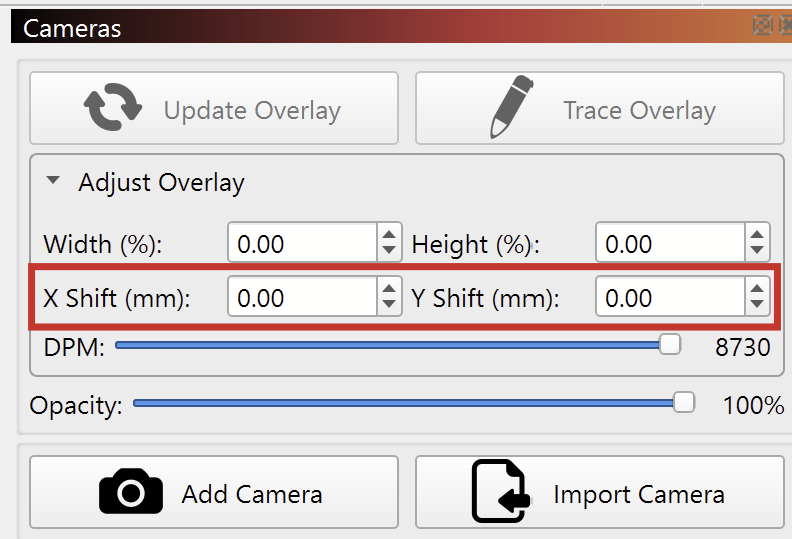
These adjustment values are set to zero, which i think is the default after running the alignment.
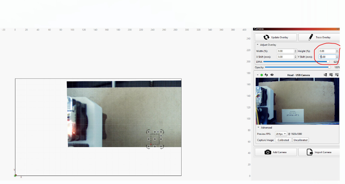
I did try adjusting these values but it just shifted the image as seen in the original post, ie there was no additional view of the workspace revealed. if the image moved up then it was just white space below it.
see this image with y-shift set to 50
That sounds strange.
To rule out an alignment/calibration error I will try a new calibration/alignment, it doesn’t take long to do after all.
The problem is often, if others cannot reproduce the error, to find the cause.
Just wanted to clarify this sentence to remove any ambiguity - its the framing which is accurate.
“The key here is that after alignment the full workspace is shown in the main window and the laser can accurately frame any object I draw.”
The problem is definitely repeatable which should be great for fault investigations. I have run the calibration and alignment many times over the last few days and so far have always got the same result.
In fact just running the alignment process clears the problem until I press the update background button.
The laser module is centred in the workspace since that is what the alignment process does. I have left it there since the most important part of the alignment is the corners as this shows the extent of the workspace.
this picture from the original post is straight after the alignment. It is the camera image used when aligning the 4 crosshairs and remains in the main window of lightburn once the alignment process window is closed. It clearly shows the crosshairs with number 1 in the top left corner. Please ignore the upside down 1 and 2 crosshairs at the bottom of the picture (i re-used the target object MDF).
The square around the number 2 top right was drawn by me after the alignment so that i could test accuracy by framing the object and watching the laser module trace around the piece on the CNC bed. which id did perfectly. I could move the square to any position within lightburn eg around the number 1 and the laser control “frame” was seen to trace on the bed around the 1.
Now if i press the “update background from camera” button I get the cropped image in the main window. see below.
So i take this to mean:
during the alignment process the camera can see the whole workspace
The alignment must be accurate since I can place shapes on the workspace and the laser “frame” is accurate.
pressing the “update background from camera” shows a cropped image
unless of course someone else knows different - happy to hear alternatives
This is the cropped view - not i had moved the square to the “3” position prior to this picture being given. The key here is not the contents of the camera image but that it is a “cropped” view and does not show the whole workspace. All camera control “Adjust Overlay” values are set to zero
Rotate the machine 180º degrees as in the picture then if your machine homes to the indicated corner, calibrate/align the camera again regarding this new “view”.
one other question. When doing the alignment I made the pattern width and height match my workspace (ie 290 wide and 170 high) with a feature width of 20mm. Is this best practice or should i use smaller parameters so that the pattern is well inside the workspace (eg 100 x 100) ?
I can’t say if it’s the best or not, but I also manually choose the size, for my 600x400 it’s 590x390 (mm) and for the code/targets I choose 30x30mm, that’s what works best here.
Remember, when you can’t place the last target plate 100% repeatable to align your work area, don’t move it. It’s the placement from the laser’s printed target template that is used for the alignment calculation.
The Official Lightburn Support may correct me on this, but I am sure that is not what the alignment is for. In fact, the alignment is to establish the boundaries of the laser module travel.
Having that module in the image may be distorting the result of the alignment process and causing the offset. In my setup, you can see I did not include the module and I easily got satisfactory results. I admit it took 2 tries, but that is because I did not understand the details of what I was supposed to do the first time.
Try Lens Calibration and Alignment without the laser module dominating the image and see if it improves your results. It can’t hurt to try. Your image also suggests the camera is not high enough to see the entire workarea.
note text in top right “the laser head has moved over the centre of the bed” - this movement to the centre of the bed is done by the Lightburn software.
I am not sure if the module may distort the results but would expect if there was a chance of that then the developers would programmatically send commands to move the head to a “safe” position.
I think the height is OK. the image does cover the full 290x170 workspace - the material that i used to etch the alignment pattern is 295x210 (ie oversized for the workspace) the circles around the crosshairs are within the corners of the workspace area as would be expected.
Note that this is a new problem on this rig. With the previous version installed (unfortunately I didn’t make a not of the version number) the alignment was good. Same camera same height same workspace size.
go into machine settings under laser tool tab , click advance and check X & Y values when i updated to 2.1.3 it changed my X Y values on board which played silly games with my camera ,
even though you may have correct dimensions in your device list if board is different you get issues
i could do the same frame etc , and got similar views or no update over lay at all,
once board and device were aligned it worked sweet as