Camera Alignment going beyond bounds

I’m on a 3018 machine and I know my bounds are 260x158

I have set my machine home position to the top right so that the camera can the work space when in the home position.

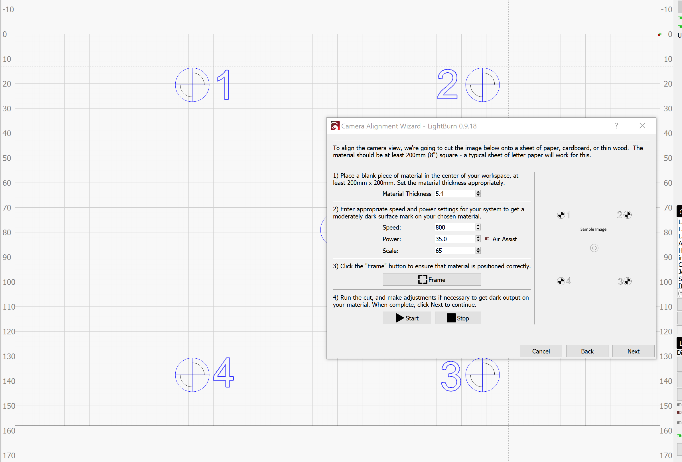
I set the Scale to 65 which should effectively laser the test pattern in a 130x130 square. But for some reason I keep hitting my limit switch when it goes to laser the #2 test pattern.

Does your machine have homing / limit switches, and has it been homed?

Yes sir. I have the Prover and have limit switches installed. I have homed it as well as set the Z to the correct height.

I also have set the home position of my machine to the top right hand corner using:

$23=0
$H

In the console, type G0 X5 Y5 and press enter. Where does your laser end up?

G0 X5 Y5 puts the laser in the bottom left hand corner roughly 40-50 cm off of the standard origin.

I just tried setting g92 x0 y0 z0 and then running it again…this time it immediately tripped my limit switch.

Ok this is starting to make more sense. If I go to origin, it doesn’t go all the way to 0, 0. So it’s almost offset. Could this be a machine setup issue? Here are my current grbl settings:

$0=10 (Step pulse time, microseconds)
$1=25 (Step idle delay, milliseconds)
$2=0 (Step pulse invert, mask)
$3=2 (Step direction invert, mask)
$4=0 (Invert step enable pin, boolean)
$5=0 (Invert limit pins, boolean)
$6=0 (Invert probe pin, boolean)
$10=3 (Status report options, mask)
$11=0.010 (Junction deviation, millimeters)
$12=0.002 (Arc tolerance, millimeters)
$13=0 (Report in inches, boolean)
$20=0 (Soft limits enable, boolean)
$21=1 (Hard limits enable, boolean)
$22=1 (Homing cycle enable, boolean)
$23=0 (Homing direction invert, mask)
$24=25.000 (Homing locate feed rate, mm/min)
$25=500.000 (Homing search seek rate, mm/min)
$26=250 (Homing switch debounce delay, milliseconds)
$27=1.000 (Homing switch pull-off distance, millimeters)
$30=1000 (Maximum spindle speed, RPM)
$31=0 (Minimum spindle speed, RPM)
$32=1 (Laser-mode enable, boolean)
$100=800.000 (X-axis travel resolution, step/mm)
$101=800.000 (Y-axis travel resolution, step/mm)
$102=800.000 (Z-axis travel resolution, step/mm)
$110=2000.000 (X-axis maximum rate, mm/min)
$111=2000.000 (Y-axis maximum rate, mm/min)
$112=600.000 (Z-axis maximum rate, mm/min)
$120=500.000 (X-axis acceleration, mm/sec^2)
$121=500.000 (Y-axis acceleration, mm/sec^2)
$122=30.000 (Z-axis acceleration, mm/sec^2)
$130=260.000 (X-axis maximum travel, millimeters)
$131=158.000 (Y-axis maximum travel, millimeters)
$132=36.000 (Z-axis maximum travel, millimeters)

The problem I’m having is in order to see my bed fully in the camera I have to invert my home to the top right hand corner. Setting the origin to the top right hand corner means everything in my work area is negative. So to go to the normal home position in the bottom left hand side I can execute G0 X-260 Y-158 and I will be in the bottom left hand normal “home” position. This seems to be an issue when working with the camera alignment as it seems to want to use absolute coordinates.

It requires absolute coordinates. The camera system works by being able to send the laser to an exact, known location. After homing, use G10 L2 P1 X-260 Y-158 and make sure $10=0. That will set your origin to the front left. We go over all of this here: Common GRBL/GCode Setups - LightBurn Software Documentation

Thanks for the reply. I will be trying this out tomorrow.

Will I need to do this command after every homing sequence?

No, the offset is remembered until it is changed, as is the $10 setting, so you only need to do it when you switch to lasering after CNC use.

So to go back to normal CNC mode would I just reverse the work flow?

$10 = 0
$23 = 3
$32 = 0
G10 L2 P1 X0 Y0

I’m wanting to write a macro that I can execute with CNCjs to make Laser setup easier in the future, but want to understand how to reverse the offset for when I go back to my home being in the bottom left with positive workspace coordinates.

Help me understand why you have to invert / use negative space to use the camera?

Yes, to revert it looks like you have the commands right, but if your machine normally works in positive space, why not leave it that way?

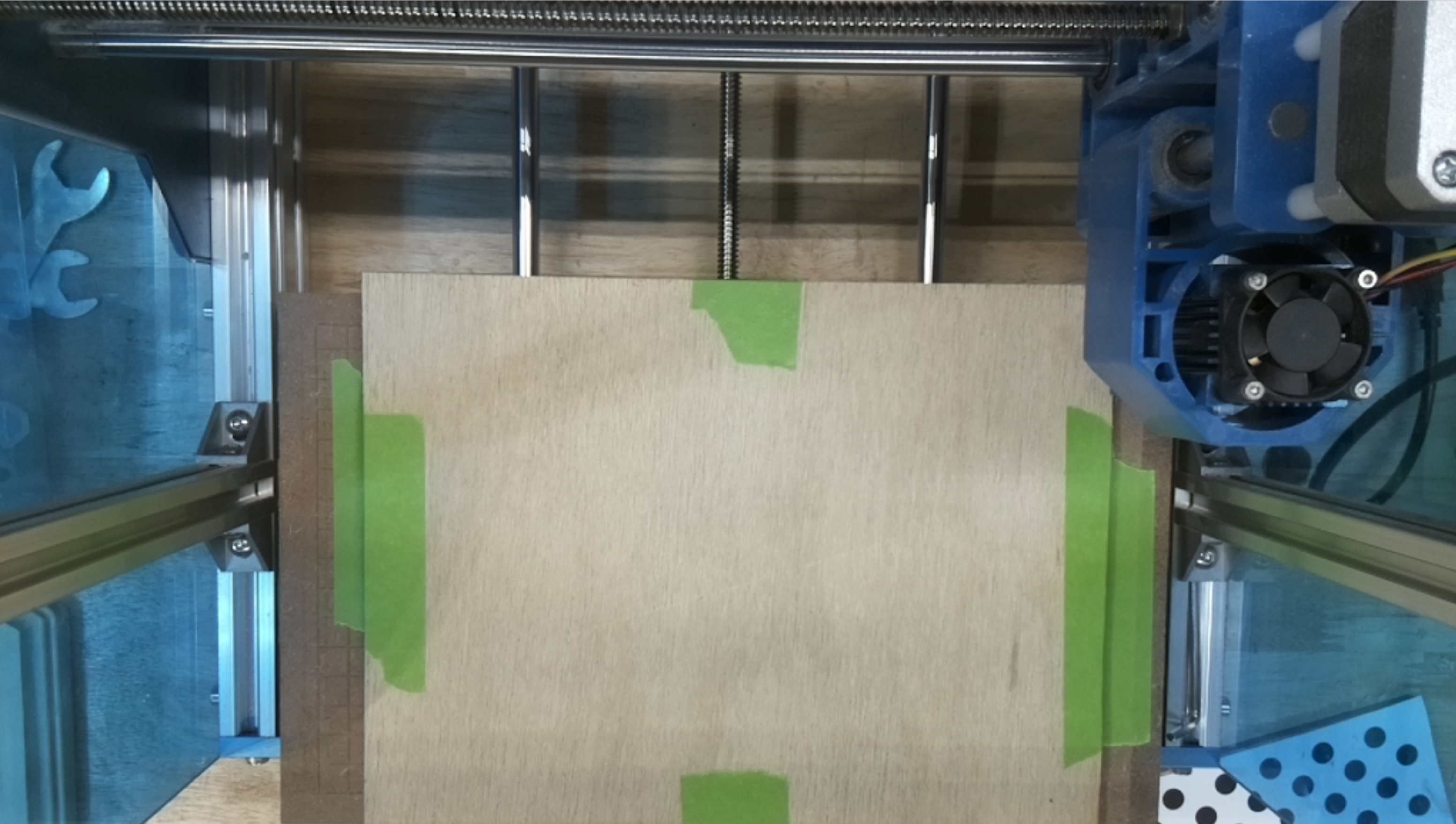
I assumed to be able to have the work area visible by the camera, I would have to invert my workspace so that when homed the work area would be under the camera and not under the z-axis gantry. Being that my y-axis moves and not the z-axis gantry, this is the only way I could figure out how to properly align the camera to the work surface.

Is there a better way?

I didn’t realize your whole Y axis moved. You are in uncharted territory there - the camera system assumes a fixed X/Y bed with a Z table. Other configurations can be made to work, but I have nothing here to replicate this setup.

My main goal for the camera is simply alignment. Once I have the camera dialed in, I plan to only use the camera to align my design on my work piece then generate g-code to send to the machine. I assume having the machine homed in the same way each time with the bed closer to the camera as in the picture above, I can achieve this. I’ll report back when I have had time to do some tests.

This topic was automatically closed 30 days after the last reply. New replies are no longer allowed.