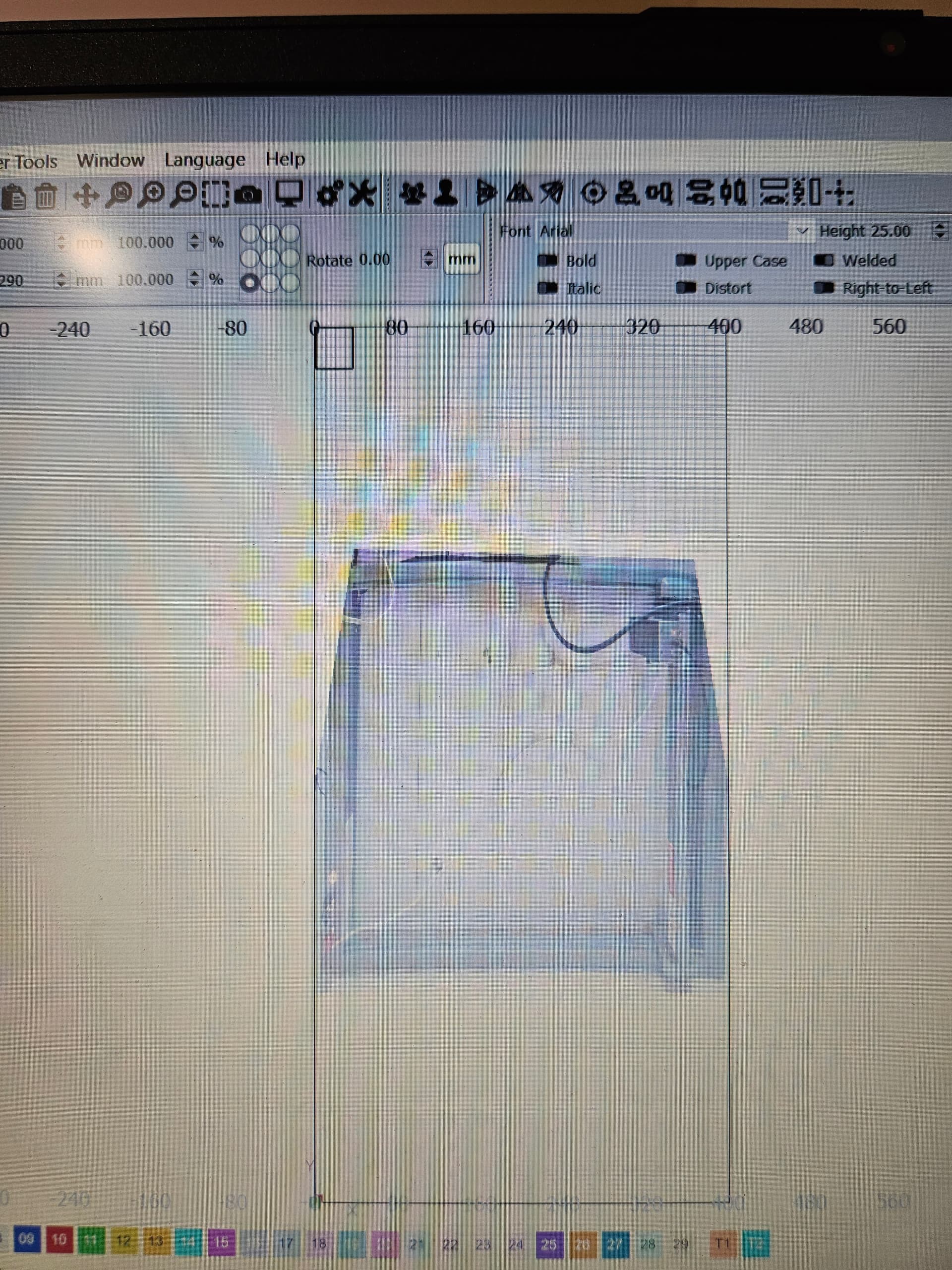
I am having a problem with camera display in Lightburn. The overlay seems to show at 400mm X 400mm, although my work area is 850mm X 400mm. I’m running Ortur Laser Master 3 with the extension on Windows 11 Pro and a Mintion 8MP 1920 X 1980 resolution lasercam.
When I try turning the display 90 degrres in settings the overlay rotates so as to crop half the image from the left.
I would expect the overlay to take up the whole work area, as I’ve seen in tutorial videos.
When I place some material in the work area and try to place test shapes for engraving and cutting I frame the area and the gantry and laser frames in positions nowhere near the material, but in a way that makes it seem like the overlay is rotated either 90 or 180 degrees relative to how the camera is positioned.
I’ve run throught the calibration and alignment wizards a few times, with the black dot test pattern completely flat. Fisheye and honeycomb are turned off and settings shows custom camera, but it won’t let me explicitly state the resolution.
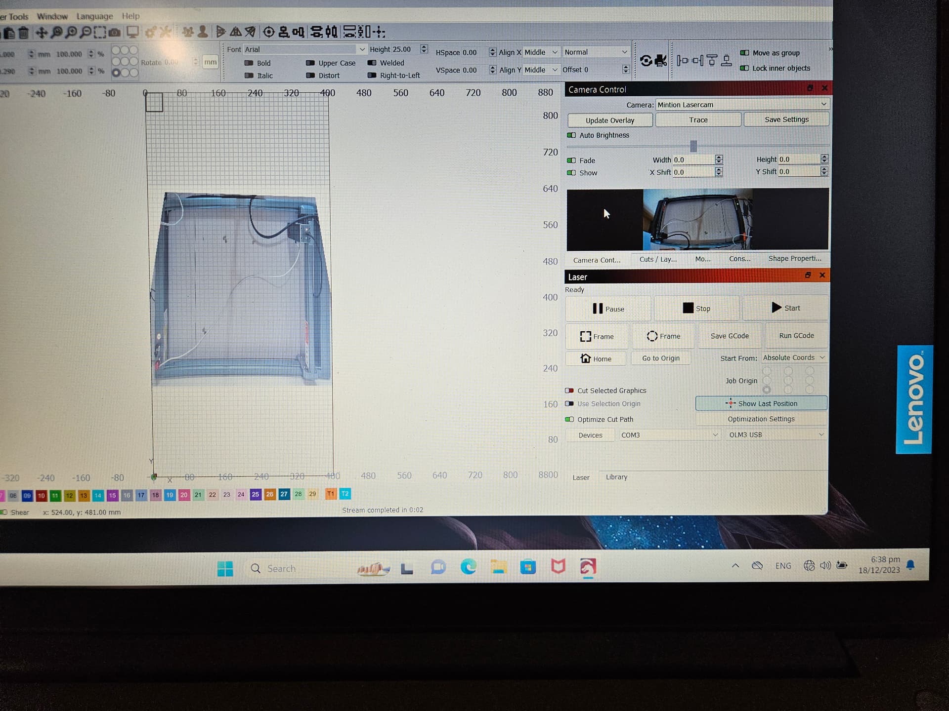
I noticed that the camera control has setting for width, height, X shift and Y shift. I playes around with these but I don’t think they worked to solve the issue.
Set these back to zero for the moment. They’re really only intended for fine tuning of the alignment.
It seems to me that the image is flipped horizontally. Meaning that the left side of the machine is appearing on the right side of the image.
From what I can tell the issues you’re seeing are due to incorrect Camera Alignment process. I suggest going through Alignment again pay special attention to the following:
burn the alignment targets as large as will fit on your bed. You can change the spacing by setting the “Scale” option
after burning the targets, you will be asked to manually zoom into the center of each target. You must do these in the correct order. I suspect you may have picked the targets out of order which is why you have the flipped image. The resulting overlay should fill the addressable area of your laser onto the workspace. You should not really be able to see the frame of the laser in the overlay.
after completing the alignment, test the overlay. If it looks reasonable but off by a few millimeters you can fine tune it with the Camera Controls. Create some designs across the workspace, then burn the design. Leave the design in place. Then capture the overlay and adjust the Camera Controls until the overlay most closely matches the location of the designs on workspace. Save the camera settings.
Thanks so much for your reply. It’s working fine now that I’ve done the calibration properly, and I only needed a some slight adjustments for the X and Y shift (around -1- for each axis are these values in pixels?). The overlay spans the X width properly but is about 10%- 15% short on the Y axis, so I’ve only got access to about 85% - 90% of the Y axis height. This works fine for me now but eventually I’ll want to recalibrate to get the full Y axis height span. I assume if I scale it up I’ll push the calibration past the X width, which I don’t want to do, correct? Is there a way to move around the bullseye circles and numbers on the Y or X axis. How would I scale it properly for an Ortur LM3 with 400mm X axis and 850mm Y axis?
If you have a larger workspace than the camera can observe, it’s best to create another laser profile with the workspace the camera can use. So add your laser as a second device, with a ~400x400 workspace in LightBurn. Then you can correctly use it. Some details: Using a camera with a diode laser - Diode Laser Wiki
I know this is a crazy thing to ask but do I leave the door up when trying to calibrate the camera lens? I have a omtech 80W AF2435 only had it around 8 months so I’m kind of new the video’s I’ve watched looks like it was open then closed for the alignment.
Note that what you’re asking about is very different than the original problem of the Topic.
In any case, without knowing anything about your system, if your camera is mounted to the door then yes, you’d typically have the door open when doing lens calibration. Note that lens calibration doesn’t actually require the camera to be mounted to the laser at all.
When doing camera alignment, the camera must be in the exact position that it will be in when used ongoing. Again, typically that will be with the door open.
So basically whenever you’re using the camera, the door will be open, then you close the door to run the job.