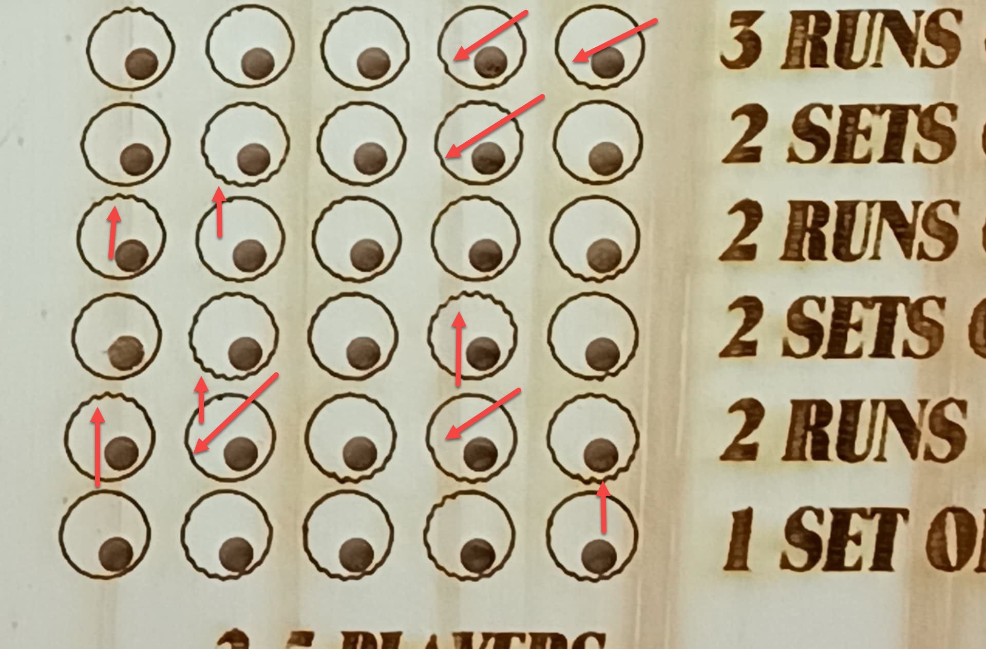
What I got from the graphic was that I see some evidence of backlash (downward arrows) and some resonance where the gantry is ringing like a tuning fork (upward arrows). I didn’t mark every instance of what I saw and it’s very consistent and not very severe.
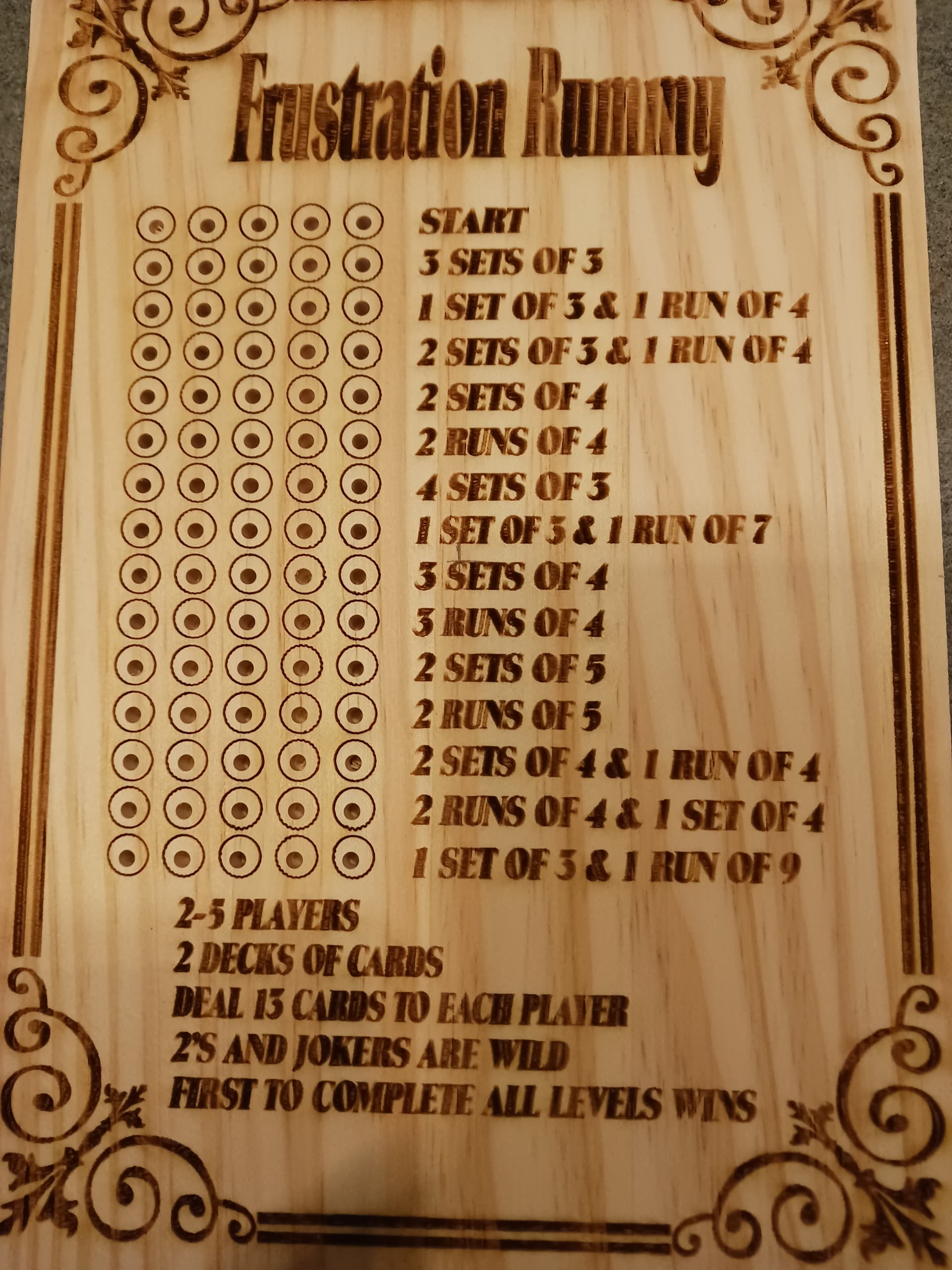
I feel that you could inform any further adjustments to settings with one or two lines of the Frustration Rummy scoreboard and save time and material costs.
Are the small dots within the circles filled left to right in the same way as the letters?
Are the dots filled before, after or line-by-line with the Lettering to their right?
It appears that the circles are a line operation. Moving 1-2% slower may be enough to get you out of the resonance.
Ok. I couldn’t figure out why the dots were offset in both axes.
The fact that they are cut out by another process is showing me that the engraving isn’t aligned.
So, new advice.
I’m now feeling that the alignment is off by the thickness of the material.
Were the four targets used for camera alignment, at the same height as the material used for the frustration Rummy boards?
A precision alignment tool is available to you in the Print and Cut tool.
Drawing an alignment register on the tool layer in the top left and bottom right circles, would allow you to align your engraving precisely with your cut holes.
If the scoring pegs have a center mark, you could put those pegs. or another custom dowel in the holes to take advantage of Print and Cut.
The best part about this is it can be used backwards. Instead of cutting out existing art, you’re mapping an engraving to an existing cut.
In context of the laser, I am not sure what “relitive Z moves” are. My bed is motorized to change the Z height, but it is just a STDP switch… up or down, manually. When I first got the laser I did a number of tests for correct Z height using the methoeds from Russ (SarbarMultimedia on Y0utube) At the time, at least, he seemed to be the guru on chinnese lasers. I worked through the process and figured out the best height for my 2" lens, and I made up a piece of styrene that I use to achieve it. I put the styrene between the bottom of the lens and the work material and raise or lower the bed (manually with a switch) tso the styrene piece just touches the bottom of the lens tube.
I did this between the lens and the dots, and the lens and the 3/4" pine. The .73 I put in the “Camera Alignment Wizard” because it asks for the material thickness. Was I not supposed to do this?
Yes, this is what was happening, and I did nothave to re-start to see that it was happening. So, what you are saying is that after I “shifted” I should also have shifted my drawn circle. I was thinking it was shifting how the program calculated where it was going to burn, as the picture moved compaired to the drawn circle, there fore, the drawn circle was not in the same place relitive to the picture. (not sure I explained my thought right, but hopefully) I will play with this tonight.
However, I am still not understanding why it worked when I got the burn cetered over the #2 target, and not on the rummy board???
It sounds like your Z-axis is entirely manual. In that case I don’t believe that should make a difference. Can you confirm that during the camera alignment process that the bed did not move after your initial focus?
If so, this should be okay.
There’s likely one position where alignment is correct. If that’s the case, then you likely have both a scale and position issue.
Unfortunatley, I am running an older version of Lightburn, and I do not have this option. Bit, I may have to upgrade.
However, this would not help on the second reason I wanted a camera. I have not brought this up as I do not an exaple to show. But I burn the names of retiring Fire Fighters in thier axes which are then mounted on a plaque.
Due to the shap and cotours of the axe handles, simply tracing the name does not show if it lines up perfectly or not. I have done a dozen or so, and have to trace each individual letter to know that it will work, a timely operation, and I hoped that a cemera would work. I don’t trust the camera, so I don’t use it. BUT I WANT TOO.
This Print and cuit method would not work for the axe handles.
In any case I suggest you follow the method that I listed earlier in optimizing your adjustment settings. That should get you extremely close assuming the lens calibration is sufficiently solid.
It is also a bit tricky, but when you print (engrave) your targets in the 4 corners, 1,2,3 and 4, this height is your 0. In the next step, 0 must therefore also be written in the material thickness and accordingly you do not touch this height until you are finished with the adjustment.
When you later work with e.g. 5 mm material, you focus your laser as you always do with your distance block and thus you have the same height for your camera again.
For fine-tuning, I recommend drawing a cross, 20-30mm with an offset of 0.5mm and cutting out the original cross. Move your test cross to another place on the bed and remember to refresh your screen. Now you can insert the first cross and align it manually over your test cross, as accurately as possible. Engrave it and refresh your screen. Now you can fine tune x and y and make a new engraving, refresh the screen again and check the result.
First of all, i want to thank everyone who has helped me work through this. I re-did everything tonight. changing the things that have been discussed here today on this thread.
AND IT WORKED
Yes the circles are off a very small amount, but I truely believe that that is because I have moved them around so much over the life of this project. I will spend some time on Fri (I have fridays off) and re-align the circles. But the fact that they are in the right spot it fantastic.